
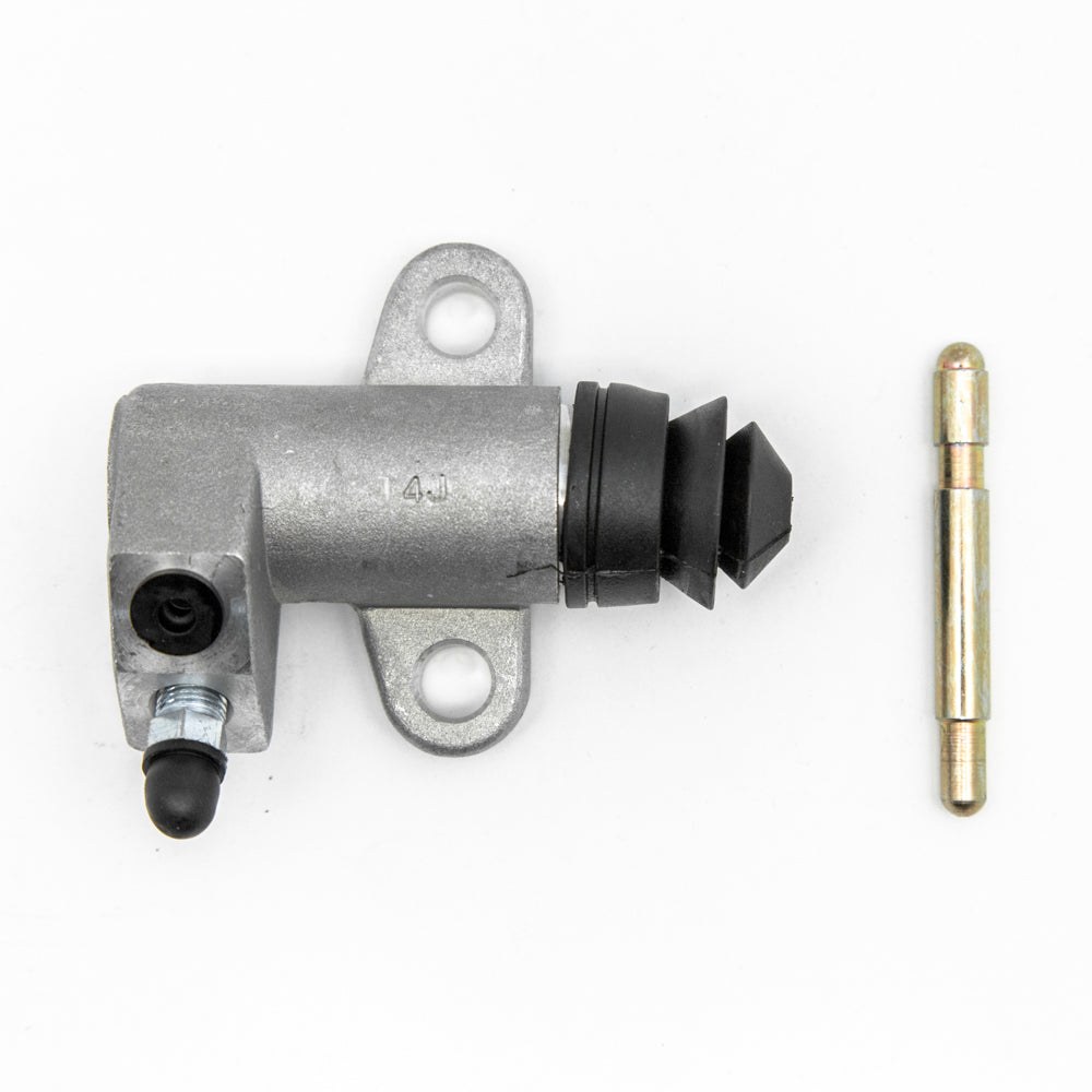

A clutch pedal that bleeds firm but fades after a few pumps, or one that feels spongy no matter what you do, usually traces back to the operating cylinder. On a 50-year-old 240Z, the piston cup inside the 15.87 mm bore hardens, swells, or tears with age — and old fluid speeds it along. The rebuild itself takes about two hours. Getting the withdrawal lever clearance right afterward is the step most people skip, and it’s the one that determines whether the clutch actually works correctly when you’re done.
What the Operating Cylinder Does
The 240Z uses a fully hydraulic clutch. Pressing the pedal drives a piston in the master cylinder, which sends fluid pressure through a steel line to the operating cylinder — also called the slave cylinder — bolted to the clutch housing. Inside, a piston pushes a rod outward, moving the withdrawal lever, which in turn presses the release bearing against the diaphragm spring fingers to disengage the clutch disc.
The operating cylinder bore is 15.87 mm, identical to the master cylinder bore. A single piston cup handles all the sealing. When that cup goes, you either lose pressure entirely or get internal bypass that eats pedal travel without moving the lever.
Specs at a Glance
| Spec | Metric | Imperial | Notes |
|---|---|---|---|
| Cylinder bore diameter | 15.87 mm | 5/8 in | Same as master cylinder |
| Max cylinder-to-piston clearance | 0.15 mm | 0.0059 in | Replace cylinder if exceeded |
| Withdrawal lever–release bearing clearance | 2.0 mm | 0.0786 in |  |
| Clutch pedal free travel | 10–15 mm | 0.394–0.590 in | Measured at pedal pad |
| Pedal height (at rest, from toe board) | 202 mm | 8.0 in |
The withdrawal lever clearance is the number to protect. Too little and the release bearing rides continuously on the diaphragm spring, burning both. Too much and the clutch won’t fully disengage at full pedal travel.
Tools
| Tool | Buy | |
|---|---|---|
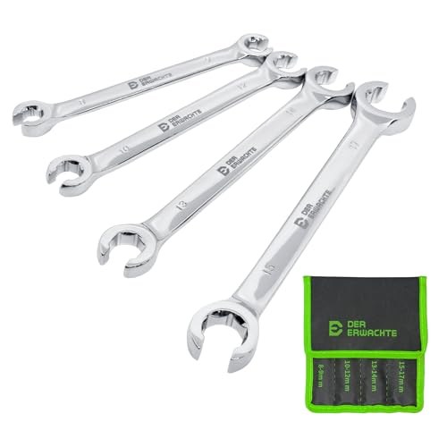 | Flare nut (line) wrench, 10 mm | Buy  |
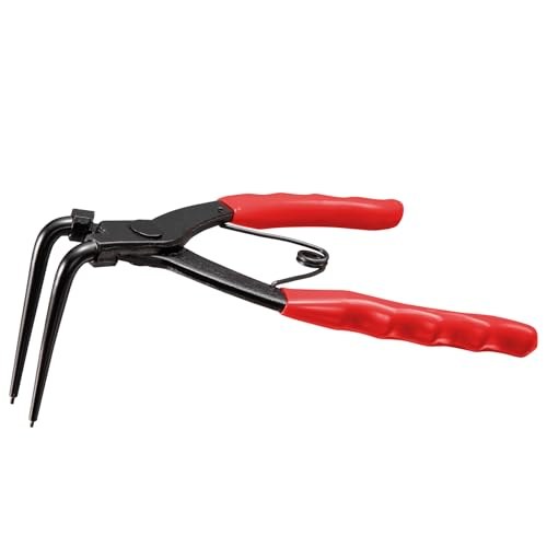 | Internal snap ring pliers | Buy |
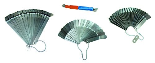 | Feeler gauge | Buy |


Also:
- Combination wrenches and socket set (10, 12 mm
- Clear vinyl tubing, approximately 6 mm ID, 300 mm length
- Clean glass jar
- Drain pan and rags (brake fluid removes paint on contact)
Parts
| Part | Recommended part | |
|---|---|---|
| Clutch slave cylinder | Buy on Amazon |
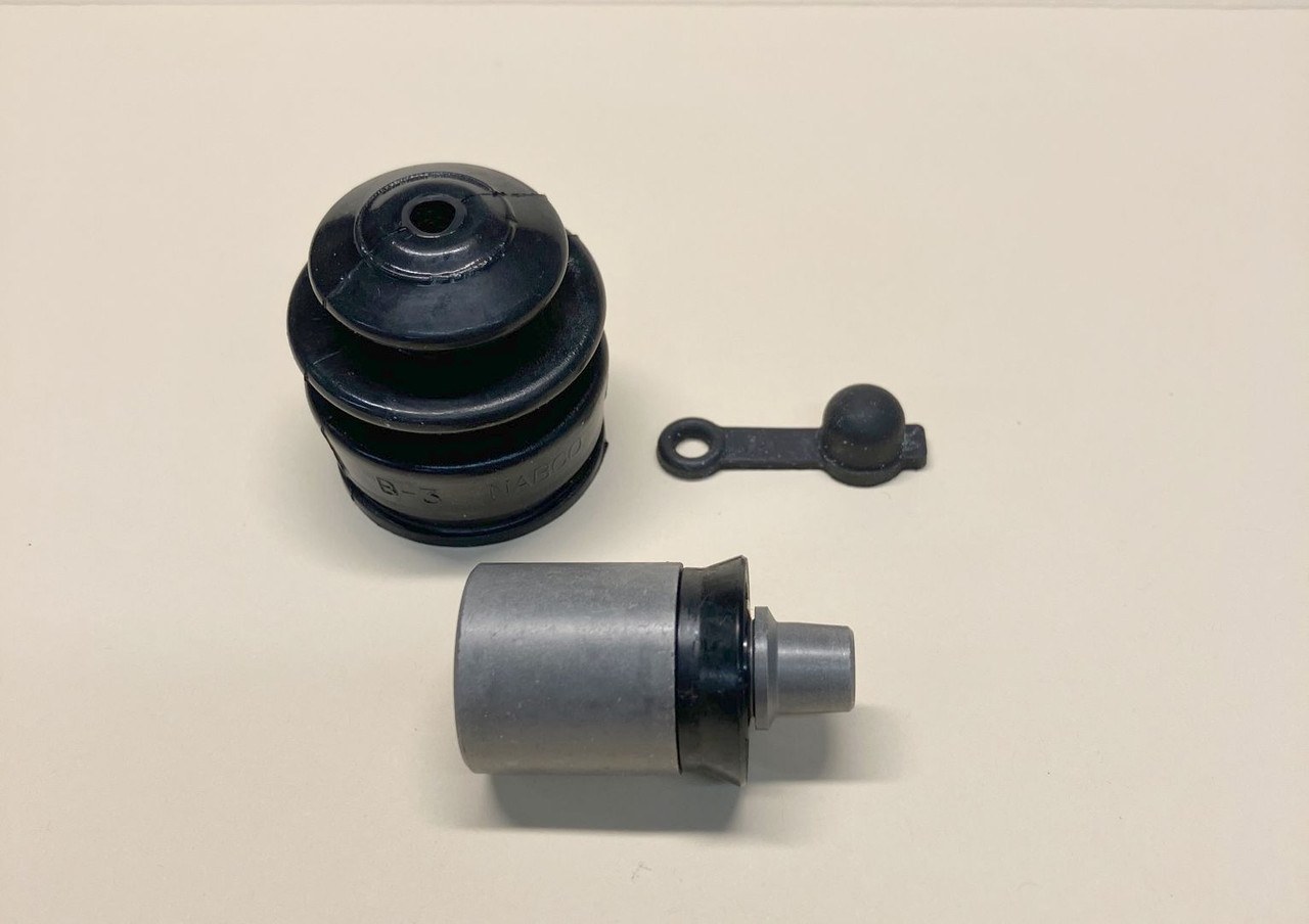 | Clutch slave cylinder rebuild kit | Buy at Datnissparts |
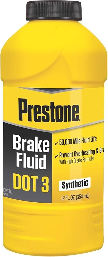 | DOT 3 brake fluid | Buy on Amazon |


Before ordering, decide which you need: if the bore wall is smooth and within the 0.15 mm (0.0059 in) clearance limit, a rebuild kit is all that’s required. A scored or pitted bore means a replacement cylinder.
Procedure
Removal

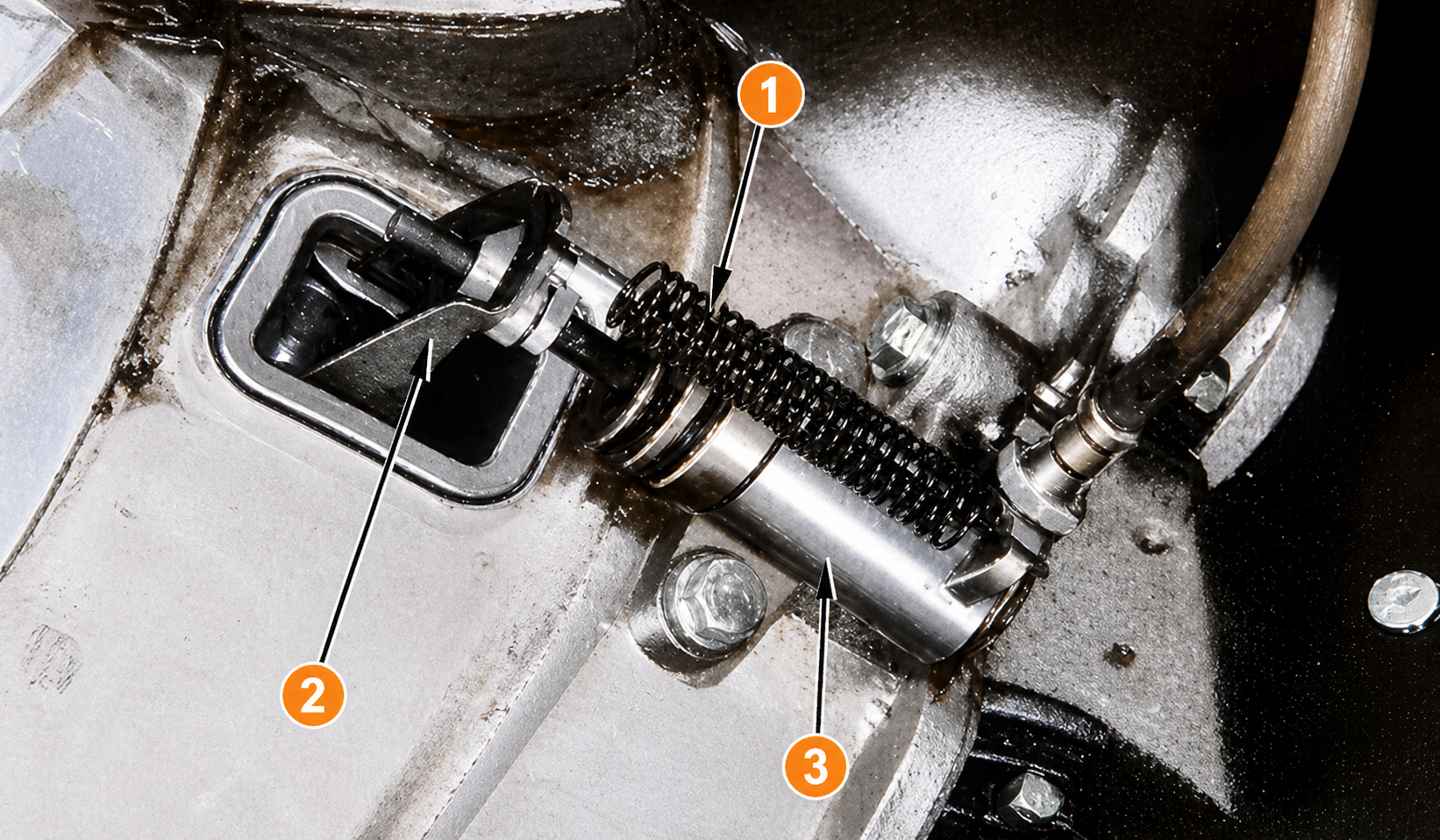
| # | Component |
|---|---|
| 1 | Return spring |
| 2 | Withdrawal lever |
| 3 | Operating cylinder |
-
Lay rags down first. Brake fluid soaks into paint in seconds. Cover anything below the master cylinder reservoir and along the clutch line before loosening anything.
-
Unhook the return spring. The coil spring runs between the withdrawal lever and the clutch housing. Unhook both ends and set it aside.
-
Disconnect the hydraulic line. Use the flare nut wrench on the fitting at the cylinder body. An open-end wrench will round the hex on the first attempt — this is not a place to improvise. Once the fitting is loose, plug or tape the open line end to slow drainage.
-
Unclip the push rod from the withdrawal lever. The rod end clips into the lever. Unclip it and swing it clear of the lever.
-
Remove the two mounting bolts and pull the cylinder free of the clutch housing.
Disassembly
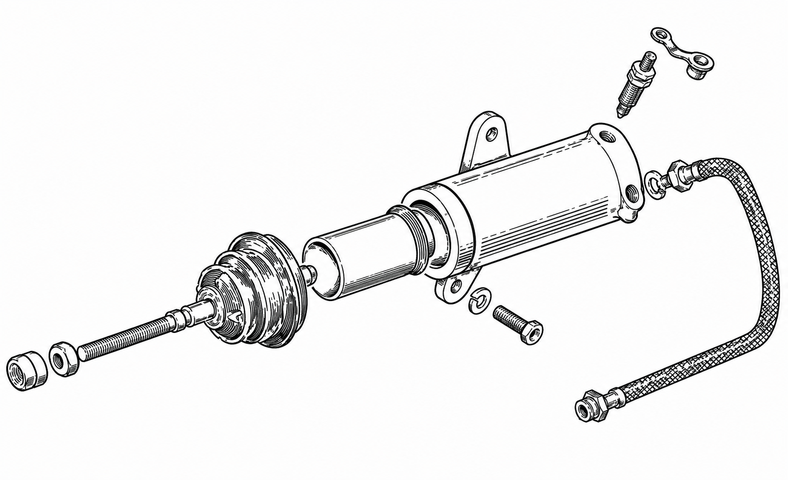
Work on a clean surface. The cylinder has five parts: dust cover, snap ring, piston, piston cup, and an internal return spring.
-
Peel the dust cover back off the push rod end to expose the snap ring groove.
-
Use internal snap ring pliers to remove the snap ring. Once it’s out, the piston, piston cup, and return spring slide straight out of the bore.

Inspection
Wipe the bore clean with a lint-free cloth dampened with fresh brake fluid.
- Cylinder bore: Run a fingernail along the bore wall lengthwise. Any groove or pit you can feel by touch means the bore is done — replace the whole cylinder. If you have a bore gauge, verify clearance against the 0.15 mm (0.0059 in) limit.
- Piston: Check for scoring and corrosion pitting. A smooth piston is reusable.
- Piston cup: Replace it any time the cylinder is apart, regardless of appearance. Rubber that looks serviceable at age 50 may already be hardened past the point of sealing reliably. The cup costs almost nothing and the whole job depends on it.
- Dust cover: Replace if cracked, torn, or brittle.
Reassembly
-
Soak the new piston cup in clean brake fluid for 5–10 minutes before installing it. This softens the lip so it seats without tearing.
-
Coat the bore and piston with fresh brake fluid. Never use petroleum-based grease — it will swell and destroy the cup.
-
Orient the piston cup correctly: cupped face inward, toward the closed end of the bore and the fluid pressure side. Installing it reversed is the single most common rebuild mistake and produces a cylinder that builds zero pressure.
-
Slide the piston cup, piston, and return spring back into the bore. Compress the assembly and snap the snap ring firmly into its groove. Give it a pull to confirm it’s seated all the way around.
-
Fit the dust cover over the push rod end.
Reinstallation
Bolt the cylinder back onto the clutch housing — the mounting bolts thread into aluminum, so snug them firmly without overtightening. Thread the hydraulic line fitting in by hand first before snugging with the flare nut wrench. Reconnect the push rod to the withdrawal lever, then rehook the return spring.
Adjusting the Withdrawal Lever
This adjustment is required after any operating cylinder work that disturbs the push rod or lever position. Do not skip it.

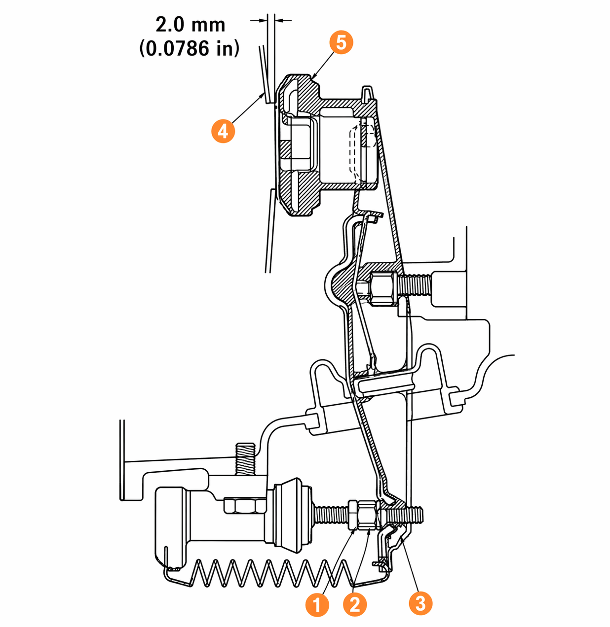
| # | Component |
|---|---|
| 1 | Lock nut |
| 3 | Withdrawal lever |
| 4 | Diaphragm spring |
| 5 | Release bearing |
The adjusting nut is at the withdrawal lever end, accessible from outside the clutch housing:
- Loosen the lock nut.
- Thread the adjusting nut inward until all clearance between the top of the withdrawal lever and the release bearing is fully eliminated — zero gap.
- From that position, back the adjusting nut out exactly 1.5 turns. Backing off 1.5 turns moves the lever end out 2.0 mm (0.0786 in), which is the correct running clearance.
- Hold the adjusting nut and tighten the lock nut against it.
Bleeding the Clutch
With air now in the system, the clutch will not work until it’s purged.
- Pull the rubber dust cap off the bleed screw on the operating cylinder body.
- Open the bleed screw approximately three-quarters of a turn. Slip clear vinyl tubing over the nipple and submerge the other end in a jar containing a small amount of fresh brake fluid — the submerged end stops air from re-entering on the pedal’s return stroke.
- Fill the master cylinder reservoir with fresh DOT 3 fluid and keep it covered between strokes.
- Have a helper depress the pedal briskly to the floor and hold it there. While it’s down, close the bleed screw. Allow the pedal to return slowly. Repeat until fluid flowing into the jar runs completely clear — no bubbles.
- On the final pump, close the bleed screw on the down-stroke, before the pedal rises. Remove the tubing and press the dust cap back on.
- Top up the reservoir and replace the cap.
Common Mistakes and Troubleshooting
Cup installed backward. If the rebuilt cylinder produces zero pedal resistance, this is the first thing to check. The cupped face goes inward. Pull the cylinder off and verify before looking anywhere else.
Open-end wrench on the line fitting. A rounded flare fitting hex is the most preventable problem on any 240Z hydraulic job. Use the right wrench.
Air won’t leave no matter how many strokes. The master cylinder reservoir is probably running dry mid-bleed, which lets air in at the inlet. Keep it full throughout. On a car that’s been sitting, the master cylinder may also have a bypassing piston cup — the two cylinders fail the same way and the master can trap air in the system regardless of how long the operating cylinder is bled.
Clutch still drags after rebuild. Check the withdrawal lever clearance. If the gap is too large, the lever can’t drive the bearing far enough to fully release the diaphragm spring. Redo the 1.5-turn adjustment.
Pedal is spongy after a clean bleed. If the fluid was bubble-free but the pedal still lacks firmness, suspect the master cylinder piston cup. Both cylinders share the same bore and fail the same way.
Fluid weeping past the dust cover after reassembly. The piston cup is reversed, was torn during installation, or the bore has a ridge or pit that prevents sealing. Disassemble and inspect the bore by feel under good light.
Verification
Before driving, confirm three things from the driver’s seat:
- Pedal free travel is 10–15 mm (0.394–0.590 in) measured at the pedal pad. Below 10 mm, the withdrawal lever clearance is too tight and the bearing is close to riding continuously. Above 15 mm, the clutch may not fully disengage.
- Clutch engages smoothly across its travel with no slipping under light load and no dragging when fully depressed.
- No fluid drips under the car after idling for a few minutes and working the pedal a dozen times.
Maintenance Notes
There’s no factory service interval for the operating cylinder seals. The practical rule is to drop in a fresh piston cup any time the hydraulic system is opened for any other reason — master cylinder, line replacement, or clutch assembly removal. The bleed is required either way, and the cup costs almost nothing. Check and top up the master cylinder reservoir once a year. Brake fluid is hygroscopic; water-saturated fluid lowers its boiling point and accelerates seal degradation over time.