
A slipping clutch on a 240Z will ruin a drive fast — and ignore it long enough and you’ll cook the disc, score the flywheel, and turn a straightforward job into an expensive one. The good news: the S30’s single dry disc diaphragm clutch is a simple, well-documented design. The bad news: getting to it means dropping the transmission. If you’re already committed, do it right.
This guide covers inspection, disassembly, parts selection, reinstallation, and the two adjustments (withdrawal lever clearance and pedal free travel) that most DIYers skip — and that cause half the comebacks.
How the System Works

The 240Z uses a single dry disc diaphragm spring clutch. The cover bolts to the flywheel and houses the diaphragm spring, which clamps the disc against the flywheel face through the pressure plate. When you depress the pedal, a hydraulic master cylinder sends fluid to a small operating cylinder mounted on the bell housing. That cylinder pushes a rod into the withdrawal lever, which pivots against the bearing sleeve and presses the release bearing into the diaphragm spring fingers — releasing clamp load and freeing the disc.
The entire clutch pedal circuit is hydraulic. There is no cable. The master and operating cylinders are both 15.87 mm (5/8 in) bore units. They’re inexpensive enough that replacing the whole cylinder is usually the practical move when one fails.
Tools and Parts
Parts
| Part | Recommended part | |
|---|---|---|
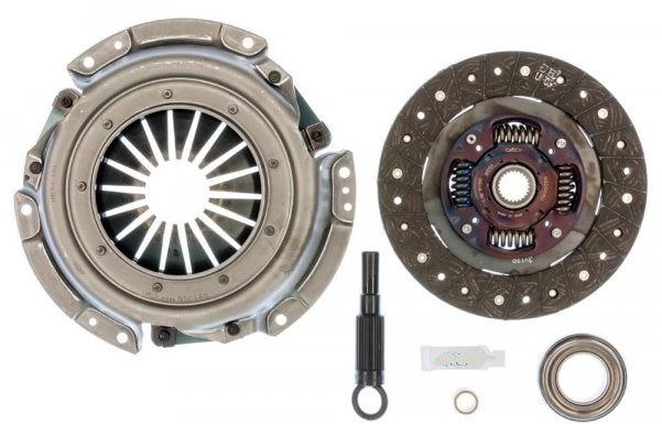
| Clutch kit | Buy  |
 | DOT 3 brake fluid | Buy |
 | Multi-purpose grease (clutch & spline) | Buy |
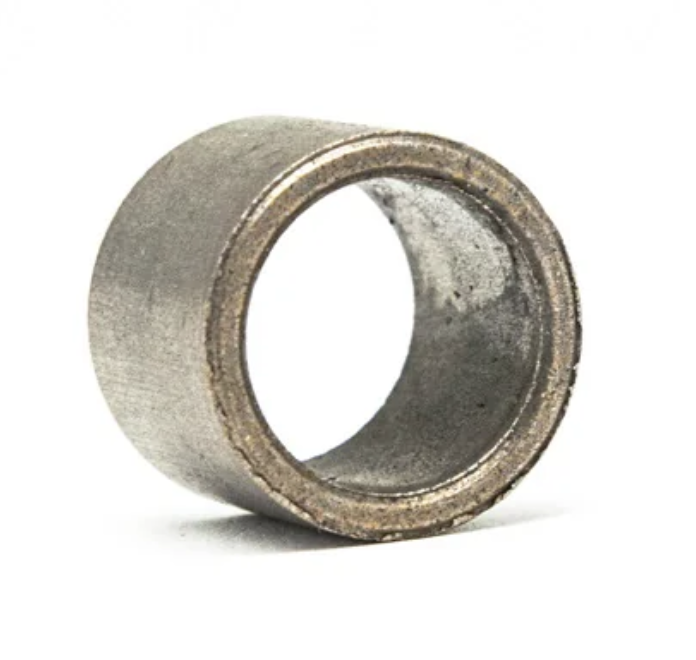 | Pilot bushing Nissan | Buy |


Always replace the disc, pressure plate, and release bearing as a set. Reusing any one of them against new counterparts wastes the job.
If the flywheel face is scored or heat-cracked, resurface or replace it before installing a new disc.
Tools
| Tool | Buy | |
|---|---|---|
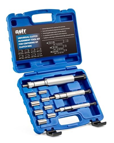 | Clutch alignment bar Most clutch kits — including the one above — ship with a plastic alignment tool that works fine, so you may already have one. Listed in case you don’t. | Buy |
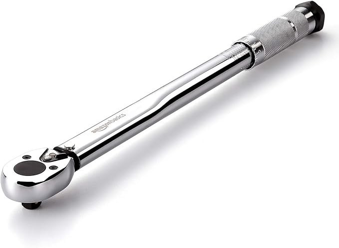 | Torque wrench, 3/8 drive (covers 15–80 ft-lb) Cover bolt torque is 17.4–18.8 ft-lb, well within this range. | Buy |
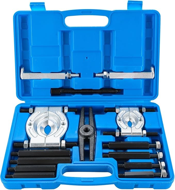 | Bearing puller / separator set Separates the release bearing from the bearing sleeve. Don’t hammer it. | Buy |
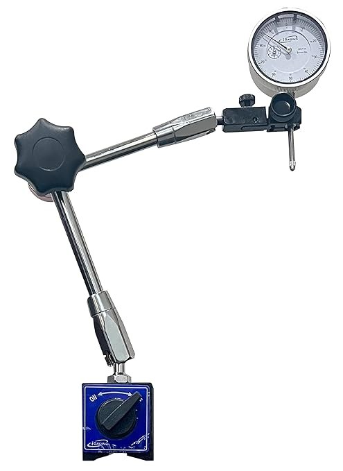 | Dial indicator with magnetic base For checking disc face runout (≤0.5 mm at 112 mm radius). | Buy |
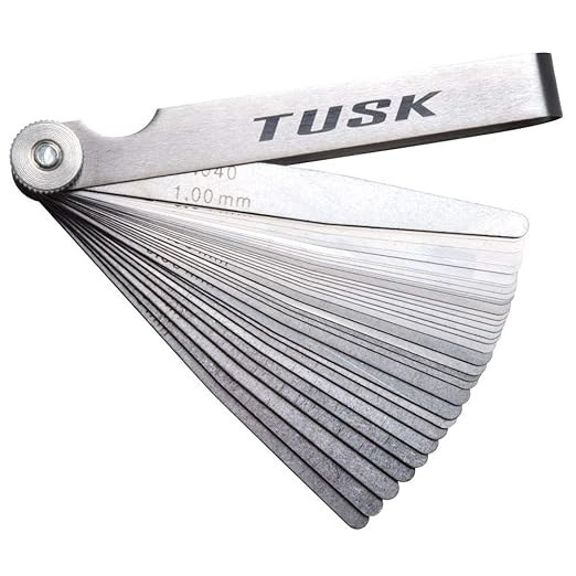 | Feeler gauges (32-blade, dual-marked) For diaphragm spring height checks if you reuse the cover. | Buy |
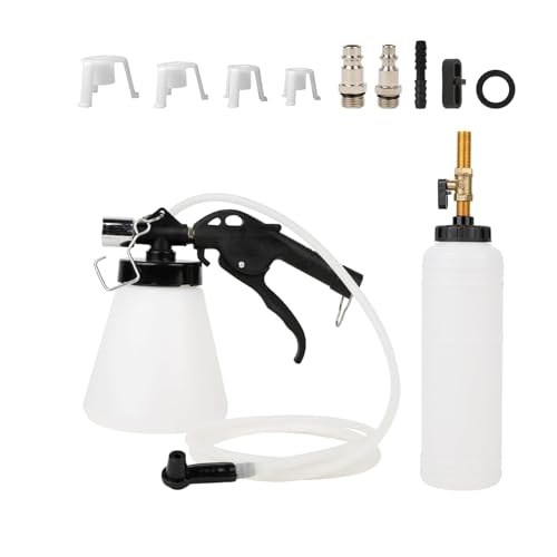 | Vacuum brake bleeder kit One-person clutch-hydraulic bleed; works without a second person on the pedal. | Buy |


Nissan special tools: The FSM calls for a clutch assembly base plate (ST20051000), distance piece (ST20058001), center pole (ST20052000), height gauge (ST20240000), and diaphragm spring adjusting wrench (ST20500000) to check and set diaphragm spring finger height. If you’re installing a new, known-good clutch cover from a reputable supplier, you can skip this step — the spring height is factory-set. If you’re reusing an old cover or suspect abuse, rent the tools or bring the cover to a shop with the equipment.
Specs at a Glance
| Spec | Value (metric) | Value (imperial) | Notes |
|---|---|---|---|
| Disc facing size (OD × ID × thickness) | 225 × 150 × 8.6 mm | 8.86 × 5.90 × 0.338 in | |
| Disc thickness, free | 8.3–8.9 mm | 0.327–0.350 in | |
| Disc thickness, compressed | 7.6–8.0 mm | 0.300–0.315 in | |
| Min rivet-head depth below facing | 0.3 mm | 0.0118 in | Replace at or below this |
| Max facing runout | 0.5 mm | 0.0197 in | At 112 mm radius |
| Max spline free play | 0.4 mm | 0.0157 in | |
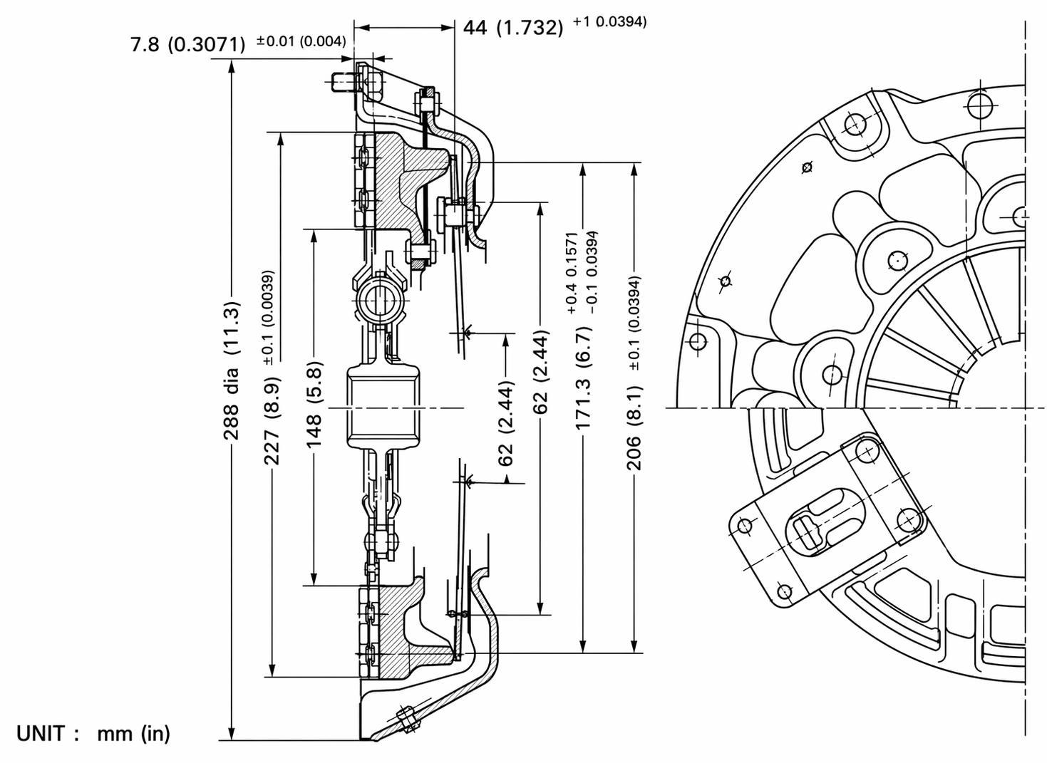
| Diaphragm spring finger height | 43.0–45.0 mm | 1.693–1.772 in | Above base plate |
| Diaphragm spring to flywheel height | 44 ± 1.0 mm | 1.73 ± 0.039 in | |
| Release bearing–to–diaphragm spring clearance | 2.0 mm | 0.0786 in | Withdrawal lever adj. |
| Clutch pedal height (not depressed) | 202 mm | 8.0 in | Both RHD and LHD |
| Pedal free travel at pad | 10–15 mm | 0.394–0.590 in | |
| Pedal effort at full stroke | 10–15 kg | 22–33 lb | |
| Master cylinder bore | 15.87 mm | 5/8 in | |
| Max cylinder-to-piston clearance (master) | 0.15 mm | 0.0059 in | Replace cylinder above this |
| Operating cylinder bore | 15.87 mm | 5/8 in | |
| Clutch cover bolt torque | 2.4–2.6 kg-m | 17.4–18.8 ft-lb | |
| Max disc plate runout (drag diagnosis) | 0.25 mm | 0.0098 in |
Procedure
Step 1 — Transmission Removal
The clutch sits between the engine flywheel and the transmission input shaft, so the engine stays in the car — only the transmission needs to come out. The FSM doesn’t include a standalone transmission-drop in the Clutch chapter; it cross-references Engine Removal, which is overkill for this job.
In short: disconnect the driveshaft, shifter, transmission mount, slave cylinder, speedometer cable, and reverse-light wiring, then slide the transmission rearward off the input shaft and lower it. The steps below pick up once the clutch assembly is accessible.
Before removing the pedal assembly, measure and record the pedal height from the toe board. You’ll need this reference when setting it back up.
Step 2 — Clutch Cover Removal


| # | Component |
|---|---|
| 1 | Clutch assembly |
| 2 | Clutch disc assembly |
With the transmission out and clutch accessible:
- Support the clutch cover by hand or with a strap — the diaphragm spring is under constant load.
- Loosen the six cover bolts in a diagonal (cross) pattern, a little at a time each pass. Don’t unload one side fully before the others — the spring will cock the cover.
- Once all bolts are loose, remove them and lift the cover and pressure plate assembly away from the flywheel. The disc will drop free.
Step 3 — Release Mechanism Disassembly

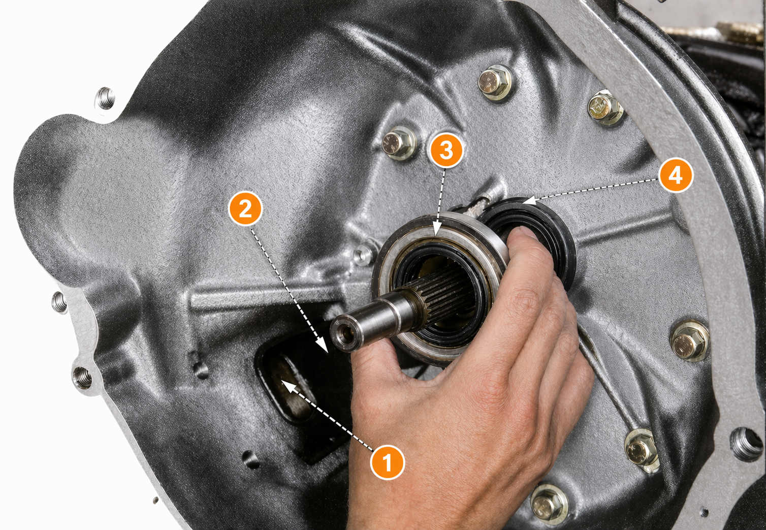
| # | Component |
|---|---|
| 1 | Dust cover |
| 2 | Withdrawal lever |
| 3 | Release bearing |
| 4 | Holder spring |
- Pull the dust cover from the clutch housing.
- Unhook the holder spring from the bearing sleeve, then separate the withdrawal lever from the sleeve.
- Slide the release bearing and bearing sleeve off the front cover together.
- Lift the withdrawal lever off the ball pin.
- Use a bearing puller to press the release bearing off the bearing sleeve. Do not hammer it.
Step 4 — Inspection
Clutch cover assembly: Look at the pressure plate face, the diaphragm spring fingers, and the cover itself. Deep grooves, cracks, or heat bluing are replacement indicators. A noisy clutch cover in service — replace it, not just the disc.
Diaphragm spring height: If reusing the cover, the diaphragm spring finger tips must measure 43.0–45.0 mm (1.693–1.772 in) above the base plate using the Nissan height gauge setup. Out-of-spec fingers can be adjusted with the adjusting wrench (ST20500000). If you don’t have the tools, a new cover from a reputable supplier is the practical path.
Disc: Check the facing surface for oil contamination, uneven wear, cracks, and loose rivets. Measure from the rivet heads to the facing surface — if any rivet is within 0.3 mm (0.0118 in) of flush, the disc is done. Check runout: mount on a shaft, spin slowly under a dial indicator at 112 mm radius. Maximum allowable runout is 0.5 mm (0.0197 in).
If the facing is lightly contaminated with oil or grease, clean with solvent and dress with a wire brush. But find and fix the leak first — a clean contaminated disc will fail again quickly.
Release bearing and sleeve: Rotate the bearing with light finger pressure. Any roughness or binding means replace it. If the withdrawal lever contact point on the sleeve has worn a visible step groove, replace the sleeve.
Pilot bushing: Check for looseness in the flywheel bore and wear on the inner diameter. If it feels sloppy, press it out and drive in a new one.
Step 5 — Reassembly: Release Mechanism
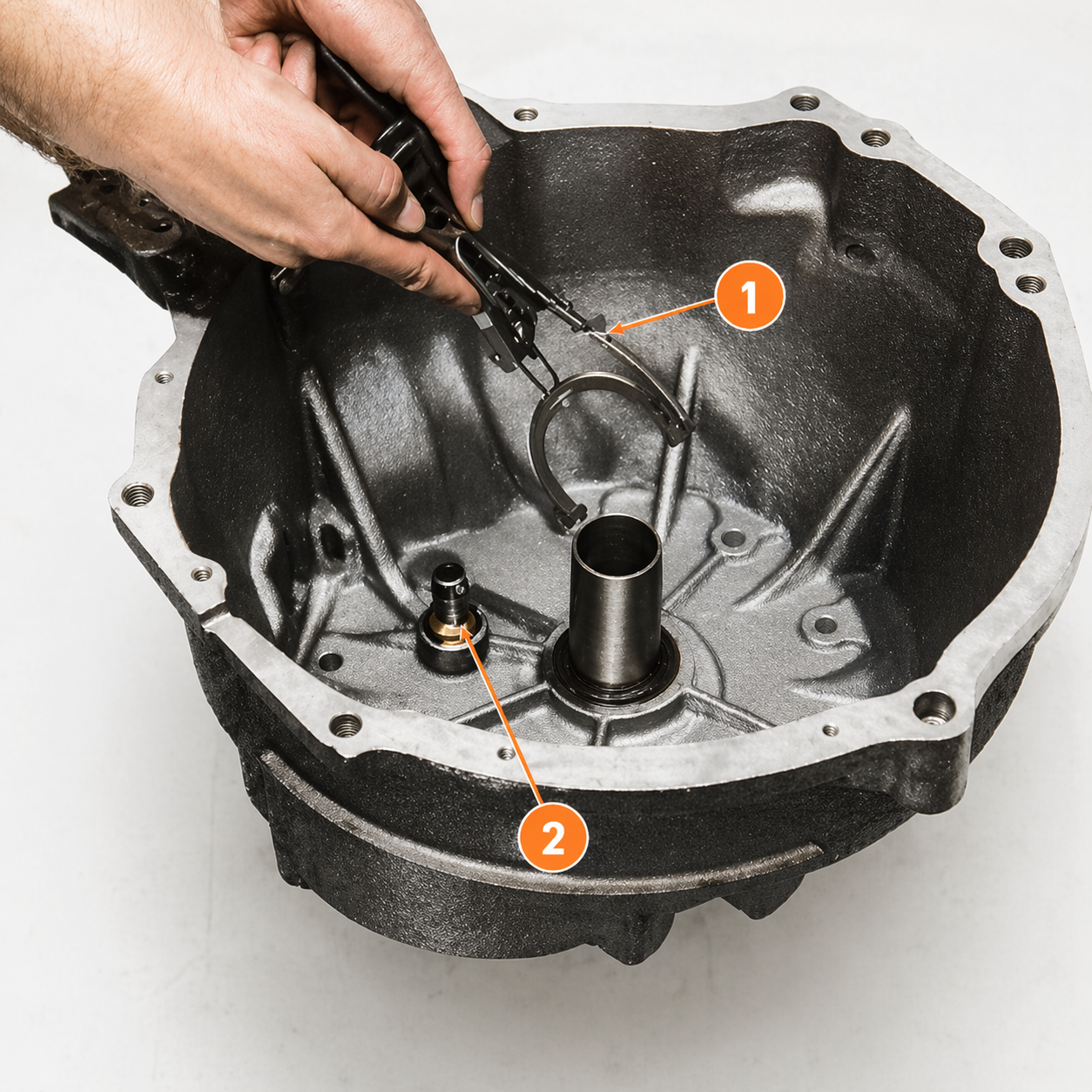
| # | Component |
|---|---|
| 1 | Withdrawal lever |
| 2 | Withdrawal lever ball pin |
- Press the release bearing firmly onto the bearing sleeve until fully seated. Spin the bearing by hand — it must rotate smoothly.
- Apply multi-purpose grease (MIL G-2108 or equivalent) to three specific locations: – Inside the bearing sleeve groove (pack it) – The withdrawal lever–to–sleeve contact point – The withdrawal lever ball pin contact surface
- Install the withdrawal lever onto the ball pin, then slide the bearing sleeve and release bearing assembly onto the front cover.
- Connect the holder spring to lock the withdrawal lever to the bearing sleeve.
- Seat the dust cover onto the clutch housing.
Step 6 — Reinstallation
| # | Component |
|---|---|
| 1 | Flywheel |
| 2 | Clutch disc assembly |
| 3 | Clutch assembly |
| 4 | ST20630000 |
- Clean the pilot bushing bore in the flywheel snout and pack it with multi-purpose grease (MIL G-2108 or equivalent).
- Slide the clutch disc onto the aligning bar. The disc is directional — most aftermarket discs label the flywheel side.
- Insert the aligning bar through the disc and into the pilot bushing. Position the disc against the flywheel face.
- Lower the clutch cover over the disc, aligning the cover’s dowel pins with the flywheel.
- Start all six bolts by hand, then snug them in a diagonal pattern.
- Torque the bolts to 2.4–2.6 kg-m (17.4–18.8 ft-lb) in a diagonal crossing sequence, in two or three passes.
- Remove the aligning bar.
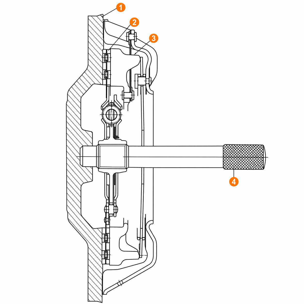
Step 7 — Withdrawal Lever Adjustment

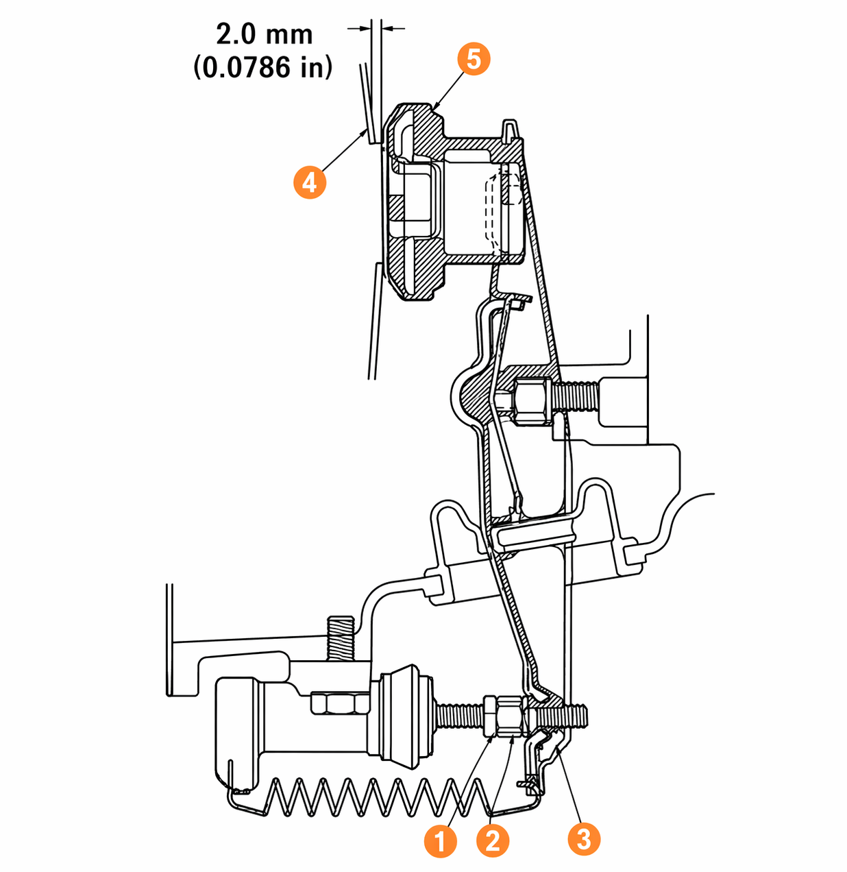
| # | Component |
|---|---|
| 1 | Lock nut |
| 3 | Withdrawal lever |
| 4 | Diaphragm spring |
| 5 | Release bearing |
This adjustment sets the clearance between the release bearing and the diaphragm spring fingers. Too little clearance and the clutch slips; too much and it won’t disengage fully.
- Loosen the lock nut on the adjusting nut at the withdrawal lever end.
- Thread the adjusting nut in until there’s zero clearance between the withdrawal lever end and the release bearing.
- Back the adjusting nut off exactly 1.5 turns from that zero-clearance point. One-and-a-half turns of the nut moves the lever end out 2.0 mm (0.0786 in), which is the target clearance.
- Hold the adjusting nut in place and tighten the lock nut.
Step 8 — Pedal Height and Free Travel Adjustment
With the transmission reinstalled and the clutch pedal connected:
- Set pedal height at 202 mm (8.0 in) from the toe board, with the pedal at rest and unloaded. Adjust by changing the master cylinder push rod length at the clevis — loosen the lock nut, turn the rod in or out, re-lock.
- Check free travel at the pedal pad — it should be 10–15 mm (0.394–0.590 in) before you feel hydraulic resistance. If it’s off, adjust the push rod length.
Step 9 — Hydraulic System Bleeding
Any time a hydraulic line was opened or the master/operating cylinder was serviced, bleed the system. Air in the line produces a spongy pedal and incomplete disengagement.
- Remove the bleed screw dust cap from the operating cylinder on the bell housing.
- Open the bleed screw about three-quarters of a turn. Slip a clear tube over the nipple and submerge the other end in a container holding a small amount of brake fluid — this prevents air from being drawn back in.
- Top off the master cylinder reservoir with fresh DOT 3 fluid.
- Depress the pedal quickly and hold it down. With the pedal held, tighten the bleed screw. Release the pedal slowly. Repeat this sequence until the fluid flowing into the container is completely free of air bubbles.
- On the final down-stroke, tighten the bleed screw, pull the tube, and replace the dust cap. Top off the reservoir.
Common Problems and Troubleshooting
The FSM’s fault table is detailed. Translated into practical terms:
Clutch slips (engine revs, car doesn’t accelerate): Worn or oil-contaminated disc is the most common cause. Check the rear main seal and transmission input shaft seal for leaks before installing a new disc. A weakened diaphragm spring or insufficient pedal return travel (springs) can also cause slip.
Clutch drags (won’t release, hard to shift): Usually air in the hydraulic circuit, incorrect withdrawal lever clearance (too much), a warped disc, or — less commonly — a disc hub that’s seized on the input shaft spline. Bleed the system first. If pedal free travel is excessive (more than 15 mm), adjust the push rod.
Noise on pedal depression: A worn, dry, or seized release bearing. The bearing is sealed and cannot be re-greased — replace it. If the bearing is fine, check pedal free travel; insufficient travel keeps the bearing in light contact with the diaphragm fingers continuously, accelerating wear.
Noise on pedal release: Disc misalignment or worn cushion springs in the disc. A misaligned disc produces noise especially at idle or low speed as the disc hub shifts against the facings. Recheck alignment on reinstallation.
Clutch grabs or chatters: Oil or grease contamination on the flywheel or pressure plate, loose disc rivets, a warped or cracked pressure plate, or a disc hub that doesn’t slide freely on the input shaft spline (clean the splines — if damage is present, replace the disc and shaft).
Drive shaft spline clearance: If you’re replacing the disc because of spline chatter, verify the new disc hub clears the input shaft to within 0.50 mm (0.0197 in) endwise and 0.20 mm (0.0079 in) crosswise. Beyond these limits, replace the shaft as well.
After the Job: What to Verify
- Pedal height 202 mm (8.0 in), free travel 10–15 mm (0.394–0.590 in).
- Withdrawal lever clearance 2.0 mm (0.0786 in).
- Fluid level in master cylinder reservoir at the full mark.
- No hydraulic leaks at either cylinder or at line fittings.
- Cold test: engage and disengage in first gear in a parking lot before driving. Listen for release bearing noise. Check for slip under load before returning the car to service.
Maintenance Interval
The disc on a properly adjusted, leak-free 240Z will typically last 60,000–80,000 miles under normal use — less on cars driven hard or in stop-and-go. Check pedal free travel every 12 months or 12,000 miles. Adjust the withdrawal lever if clutch engagement moves to the top or bottom of pedal travel. Inspect master and operating cylinder boots for weeping fluid at the same interval.
Sources
- Datsun 240Z Factory Service Manual, Section CL (Clutch), pages CL-1 through CL-14
- FSM page labels cited: CL-2, CL-5, CL-10, CL-13, CL-15, CL-16, CL-19