
Lower your 240Z more than an inch and the factory front suspension will pull negative camber with no built-in way to correct it. The S30 uses a MacPherson strut design with a fixed rubber top mount, and the FSM makes the limitation clear: neither camber nor caster can be adjusted on the stock car — only toe-in and ride height. Camber plates replace that fixed rubber mount with an adjustable eccentric that lets you dial the strut angle in from above.
Skip this upgrade on a lowered car and you’ll chew through the inner tire edges, fight understeer on corner entry, and run alignment specs that no shop can correct with the factory hardware still in place.
How the Stock Top Mount Works
The strut tower stack is three pieces: a rubber-isolated insulator, a thrust bearing, and an upper spring seat. The insulator bolts to the strut tower through three studs, the piston rod passes up through the center, and a self-locking nut clamps it all together. Because the insulator seats concentrically in the tower, the strut angle is fixed by the chassis stamping — there are no slots or eccentrics to move.
A camber plate replaces the insulator (and typically the spring seat) with a slotted or eccentric mount. It uses the same three tower studs, but a second capture allows the piston rod to sit off-center. Shift the rod inboard and you add negative camber; shift it outboard and you reduce negative camber or go positive.
For a mildly lowered street car, −1.0° to −1.5° per side is a workable target. For autocross or track use, −2.0° to −3.0° is common. Your alignment shop sets the final number — the plates just give them range to work with.
Factory Alignment Specs
These are the factory figures. They apply to the stock-height car and tell you what you’re starting from before the plates go in. The camber tolerance without load spans roughly −20′ to −80′ (about −0.3° to −1.3°), which explains why a stock car sitting a bit low can already show uneven wear.
| Parameter | Without Load | With Standard Load |
|---|---|---|
| Camber | −50′ ±30′ | +30′ ±30′ |
| Caster | 2°55′ ±30′ | 3°00′ ±30′ |
| Toe-in | 2–5 mm (0.079–0.197 in) | 0–3 mm (0.000–0.118 in) |
| King pin inclination | 12°10′ ±30′ | 12°25′ ±30′ |
Caster is also preset on the stock chassis and cannot be adjusted without aftermarket hardware. Some camber plate kits include minor caster correction — confirm with your specific kit documentation.
Torque Specs
These are the two fasteners you’ll be dealing with at the strut top.
| Fastener | Torque |
|---|---|
| Piston rod self-locking nut (center nut) | 7.5–9.5 kg-m (54.2–68.7 ft-lb) |
| Strut-to-body mounting nuts (3×) | 2.5–3.5 kg-m (18.1–25.3 ft-lb) |
Both fasteners require new self-locking nuts on every disassembly — the FSM requires this, and a used nylon-insert nut will not provide reliable clamp load.
Tools
| Tool | Buy | |
|---|---|---|
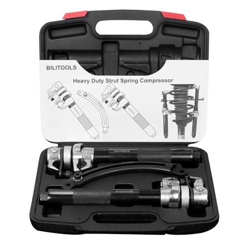 | Coil spring compressor — strut type (mandatory) MacPherson-style with safety hooks. Generic two-jaw clamps are NOT acceptable for this job — the spring is under enough load to kill you. | Buy ↗ |
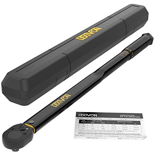 | 1/2″ drive click torque wrench, 25–250 ft-lb Strut piston rod nut spec is ~70 ft-lb; 1/2″ drive gives clean control. | Buy ↗ |
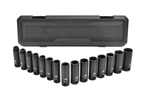 | 1/2″ drive metric deep socket set (10–24 mm) Deep sockets are required for the strut center nut. Covers the 14, 17, 19, 22 mm hardware on the 240Z’s strut tower. | Buy ↗ |
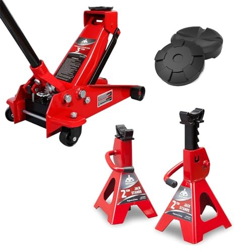 | 3-ton low-profile floor jack + jack stands Whole car raised, both wheels off, stands placed before any spring work. | Buy ↗ |
 | Multi-purpose moly grease (MIL G-2108 / 10924 compatible) A small dab on the bearing and contact surfaces during reassembly. | Buy ↗ |
Also:
- Piston rod counter-hold tool — most camber plate kits include one. Confirm before you order separately.
- Alignment shop appointment for after the install. Do not skip; even a careful eyeball setup needs a rack to confirm toe and final camber.
Parts
| Part | Recommended part | |
|---|---|---|
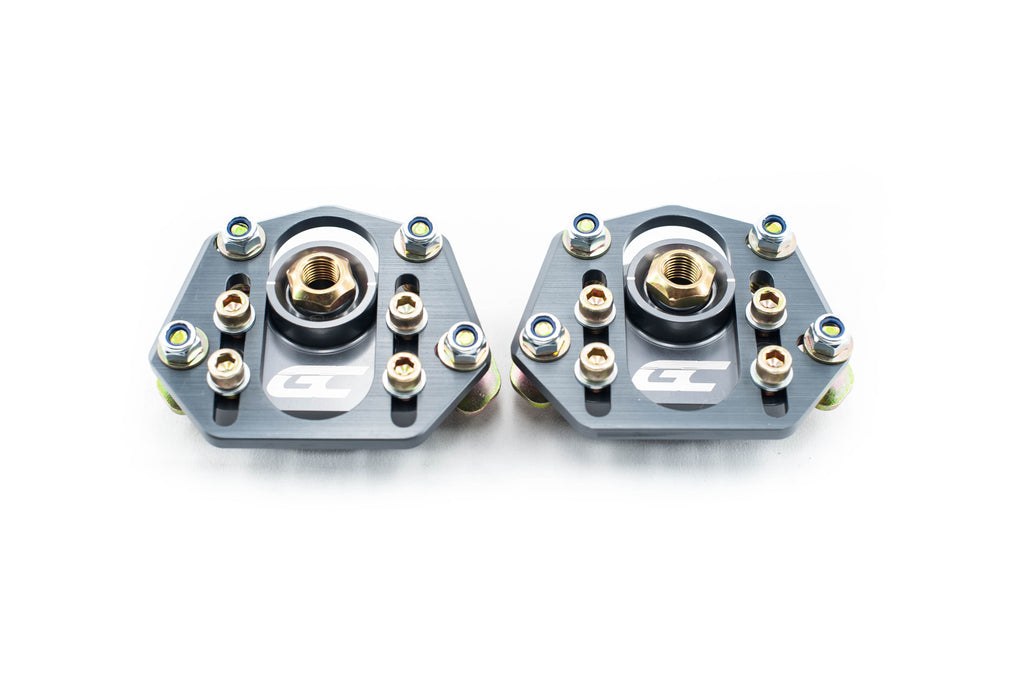 | Camber/Caster Plate (Pair) | — |
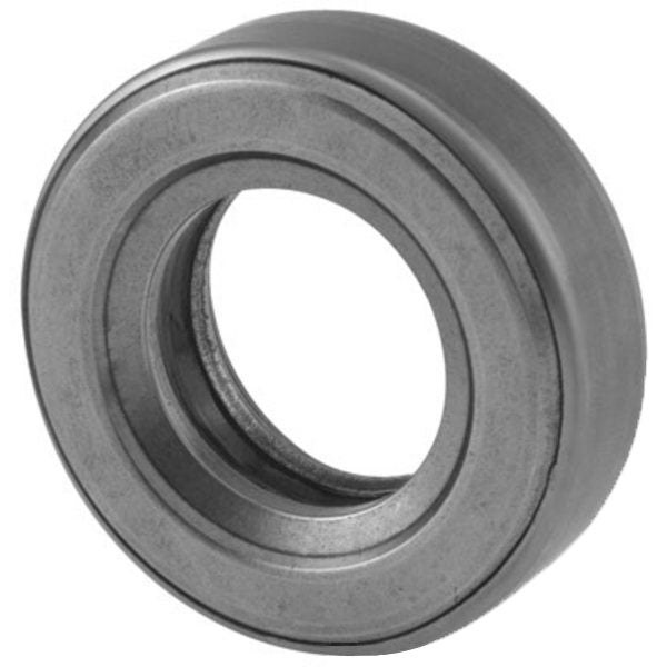 | Front strut mount bearing | — |
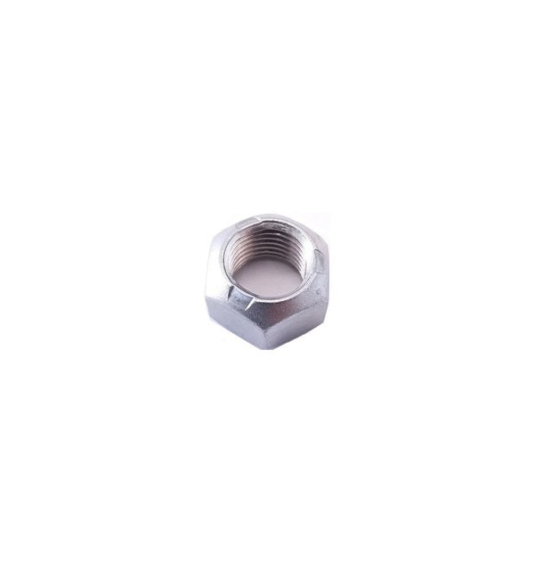 | Strut piston rod self-locking nut (M12) | — |
Most kits ship with new center hardware. Verify before ordering separate locknuts. The strut mounting bearing should be replaced if it produces any roughness or noise when rotated by hand — replace it now rather than pulling the strut top apart again in six months.
Procedure
1. Raise the Car and Pull the Wheels
Jack up the front, support on stands at the subframe. The suspension must be fully drooped and unloaded during disassembly. Pull both front wheels.
2. Compress the Front Spring
Clamp a spring compressor to the coil while the strut is still installed. Compress until the strut mounting insulator — the large rubber puck at the strut top — spins freely by hand, indicating the spring is fully unloaded from the upper seat. Do not compress more than needed to achieve this.
Do not skip this step and crack the center nut with a loaded spring. The stored energy will move the piston rod the instant the nut clears; best case you damage the rod threads.
3. Locate the Strut Tower Hardware
Open the hood. The strut tower is the domed stamping on each side of the engine bay. Three studs poke through it and hold the strut assembly to the body; the piston rod exits through the center hole. The three outer nuts (2.5–3.5 kg-m / 18.1–25.3 ft-lb) secure the strut to the chassis. The center self-locking nut (7.5–9.5 kg-m / 54.2–68.7 ft-lb) clamps the piston rod to the insulator assembly.
4. Remove the Center Nut
Hold the piston rod stationary with your counter-hold tool at the rod’s top flat or hex. Break loose the center self-locking nut and spin it off. Set it aside — it doesn’t go back on.
5. Remove the Three Tower Nuts
Back out the three tower stud nuts. The strut is now unrestrained at the top but still supported by the compressed spring below and the ball joint at the bottom.
6. Pull the OEM Top Mount Stack
Lift off the strut mounting insulator, thrust bearing, and upper spring seat. While they’re in your hands:
Insulator: You’re replacing this with the camber plate regardless. Inspect it anyway if you’re keeping the stock setup as a backup.
Strut mounting bearing: Spin it between your fingers. Smooth and drag-free is fine. Any roughness, clicking, or visible play: replace it. Pack the new bearing with multi-purpose grease (MIL G-2108 or 10924) before installation.
Upper spring seat: Most camber plate kits include a replacement. Check your kit’s contents list.
7. Install the Camber Plate
Assembly order varies by manufacturer — follow your kit’s instructions for the specific sequence. The general flow:
- Thread the plate’s upper half onto the piston rod and seat it on the three tower studs.
- Position the plate at center (zero adjustment) for now.
- Install the spring seat and bearing per the kit’s order.
- Thread the new center locknut on by hand.
- Snug the three tower nuts by hand only.
Do not torque anything yet — you need the plate to slide when you set initial camber.
8. Set Initial Camber
With everything snug but not torqued, slide the piston rod to your intended starting position. Most kits have degree markings on the plate or a visible slot.
Do not set the plate at maximum negative camber before alignment — leave room to adjust in either direction at the shop. A reasonable starting position for a street car is −1.0° to −1.5°; for a track-focused build, −2.0° to −2.5° is a common starting point. The shop will refine it.
9. Torque in Sequence
Hold your camber position and torque:
- Three tower stud nuts: 2.5–3.5 kg-m (18.1–25.3 ft-lb)
- Center piston rod locknut: 7.5–9.5 kg-m (54.2–68.7 ft-lb)
Do both sides before releasing either spring compressor.
10. Release the Compressor and Reinstall Wheels
Slowly back off the spring compressor and watch the spring seat. The coil end must locate cleanly in the lower seat and contact the upper seat correctly — the FSM specifically calls out correct spring seating during strut reassembly. If the spring shifts or binds, stop and reseat it before releasing pressure.
Reinstall the wheels, lower the car.
Common Mistakes
Skipping the spring compressor. There is no safe workaround. Compress the spring first.
Torquing the center nut with an uncompressed spring. The spring pushing up on the seat prevents proper clamping of the piston rod. Compress first, set camber, torque.
Setting camber on jack stands. Strut geometry shifts under vehicle weight. Get the car on the ground and aligned — don’t assume your jack-stand setting is your final setting.
Reusing the self-locking nut. One use. The FSM says so; ignore it and the nut will back off under vibration.
Leaving the strut mounting bearing in. If the bearing is rough or clunks on steering input, you’ll be pulling this apart again immediately. Replace it now.
Forgetting to torque the tower nuts at load. Some installers torque everything on stands, then the body shifts when the car’s weight comes on and the plates bind at the wrong position. If your kit instructions say to torque at ride height, follow that sequence.
Alignment After Installation
Book the alignment before you drive more than a block. The plates are set to an approximation until the shop locks them in.
Front alignment targets post-install:
| Parameter | Street | Autocross/Track |
|---|---|---|
| Camber | −1.0° to −1.5° | −2.0° to −3.0° |
| Toe | 0 to 2 mm toe-in | 0 mm to slight toe-out |
| Caster | As-found (non-adjustable unless kit provides) | Same |
Toe spec: factory calls for 2–5 mm total toe-in without load and 0–3 mm with standard load. A slight toe-in bias is appropriate for street use; track use often favors zero or light toe-out for turn-in response.
Recheck Interval
- First 500 miles post-install — plates settle, nuts may relax slightly
- After any solid impact (curb strike, deep pothole)
- After each track day
- Any time you adjust ride height
Torque-check the three tower nuts and center locknut at each interval. These are structural fasteners; treat them accordingly.
