
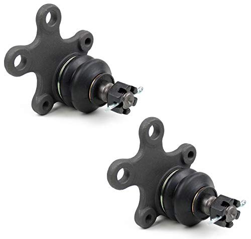
The lower ball joint is the pivot that lets the front wheel steer while the suspension travels up and down. When it wears out, the first signs are a clunk over bumps, vague on-center steering, and a slight shimmy at speed. Let it go too far and the excessive end play can cause the front tire to tuck under during hard braking or cornering. On a 50-year-old 240Z, this isn’t a hypothetical — it’s a routine failure mode.
The 240Z lower ball joint is a sealed, non-rebuildable unit. Regular greasing every 50,000 km (30,000 miles) or two years will push the wear curve back, but once it’s past service limit, the whole assembly comes out.
How It’s Built and Why It Wears
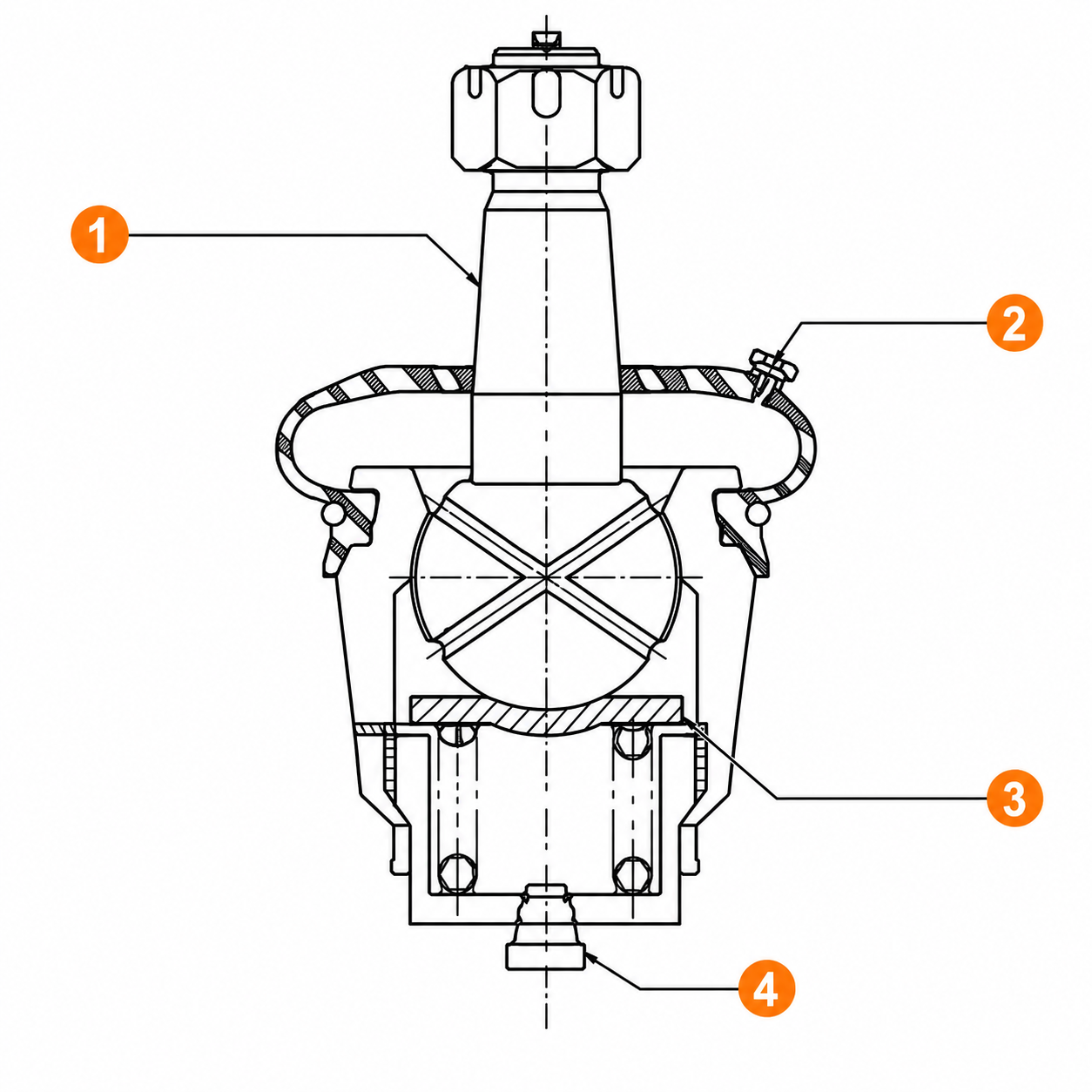
| # | Component |
|---|---|
| 1 | Ball stud |
| 2 | Grease bleeder |
| 3 | Spring seat |
| 4 | Plug |
The 240Z runs a MacPherson strut front suspension. The strut handles vertical loads; the transverse link (lower control arm) handles lateral forces, and the lower ball joint is where those two jobs meet. The ball joint housing bolts to the transverse link. Its tapered stud inserts upward into the knuckle arm at the base of the strut spindle, secured there by a castle nut and cotter pin plus a pair of clamp bolts that grip the spindle ears around the stud.
Internally, the joint uses a spring-loaded bearing and fluid packing. As the bearing surface wears, axial end play increases and shaking torque drops. On a car that hasn’t been greased regularly, the dust cover eventually cracks and lets in grit, accelerating wear dramatically.
Specs at a Glance
Ball joint service limits
| Measurement | Factory Spec |
|---|---|
| End play, axial direction | 0.03–0.6 mm (0.0012–0.0136 in) |
| Shaking torque | 20–90 gr-cm (0.28–1.25 in-oz) |
| Shaking force at cotter pin position | 3.9–17.3 kg (8.6–38.1 lb) |
Replace the joint if end play exceeds 0.6 mm or shaking torque falls below 20 gr-cm. A cracked dust cover is an automatic replacement regardless of measured play.
Torque specs — all fasteners you’ll disturb
| Fastener | Torque |
|---|---|
| Ball joint castle nut | 5.5–7.5 kg-m (39.8–54.2 ft-lb) |
| Ball joint body bolts (to transverse link) | 4.9–6.3 kg-m (35.4–45.6 ft-lb) |
| Knuckle arm clamp bolts | 7.3–10.0 kg-m (52.8–72.3 ft-lb) |
| Transverse link mounting bolt | 11.0–13.0 kg-m (79.6–94.0 ft-lb) |
| Compression rod — transverse link side | 5.0–6.2 kg-m (36.2–44.8 ft-lb) |
| Compression rod — body side | 4.5–5.5 kg-m (32.6–39.8 ft-lb) |
| Stabilizer connecting rod to transverse link | 1.9–2.6 kg-m (13.7–18.8 ft-lb) |
Critical: The transverse link mounting bolt must be final-torqued with the vehicle at curb weight — equivalent to two passengers aboard — not with the suspension hanging. Torquing it unloaded preloads the bushing from the start and shortens its service life significantly.
Tools
| Tool | Buy | |
|---|---|---|
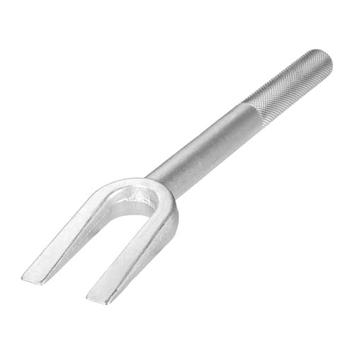 | Ball joint separator (pickle fork) or dedicated ball joint press kit | Buy ↗ |
Also:
- Floor jack and two jack stands rated for the vehicle
- Torque wrench, 0–15 kg-m (0–110 ft-lb) range
- 1/2-inch drive metric socket set, plus a 3/4-drive breaker bar for the transverse link mounting bolt
- Combination wrenches, metric
- Hammer
- Grease gun
- Penetrating oil
- Wire brush
Parts
| Part | Recommended part | |
|---|---|---|
| Ball joint, front lower | Buy on Amazon ↗ |
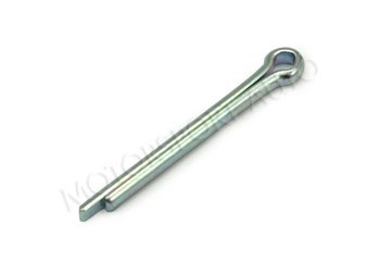 | Cotter pin, front hub | Buy at The Z Store ↗ |
 | Multi-purpose grease | Buy on Amazon ↗ |
 | Transverse link bushing | Buy at ZCarDepot ↗ |
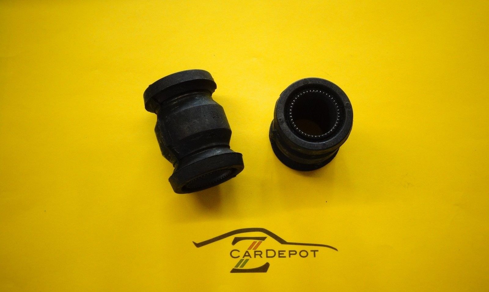
With the transverse link already out of the car, inspect the pressed-in rubber bushing at the inner pivot. If the rubber is cracked, hardened, or the inner tube moves within the outer, replace the bushing now. Pressing it in and out requires a bushing driver; the factory tool is special tool ST36710000, though any shop press with the right diameter driver will work.
Removal
1. Break the lug nuts loose while the wheel is still on the ground. Jack the vehicle and support it on stands under the chassis — never on the control arm. Remove the front wheel.
2. Soak the fasteners. Hit the compression rod bolts, transverse link mounting bolt, knuckle arm clamp bolts, and the castle nut with penetrating oil and give it 15 minutes.
3. Disconnect the stabilizer bar from the transverse link by removing the connecting rod nut.
4. Remove the compression rod from the transverse link. Loosen the transverse link end nut first, then the body-side nut, and pull the rod free.
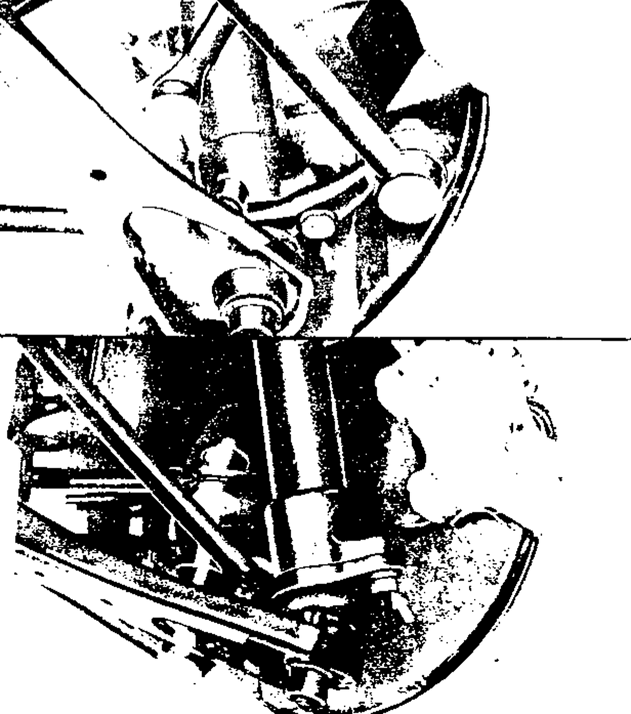
5. Loosen the two knuckle arm clamp bolts. These pass through the lower ears of the strut spindle housing and clamp around the ball joint stud. Back them off until the spindle ears can spread and release the stud taper — you don’t need to pull the bolts entirely, just relieve the clamping load.
6. Break the ball joint stud taper free from the spindle. With the clamp bolts loose, use a ball joint separator or a sharp hammer blow to the spindle housing — not the stud itself — to shock the taper loose. The transverse link will drop downward once the stud is free.
7. Loosen the transverse link mounting bolt at the inner pivot on the suspension member and swing the link clear.
8. Pull the cotter pin from the castle nut on the ball joint stud. Remove the castle nut. If the stud spins, grip the stud flats with locking pliers while turning the nut.
9. Remove the ball joint body bolts from the transverse link. The ball joint is now free.
Before discarding the old joint, this is a good time to verify end play with a dial indicator if you want the data for your records. More than 0.6 mm axial play means it was overdue.
Inspection Before Reassembly
Knuckle arm bore: The tapered hole where the ball stud seats must be clean and free of cracks or galling. Any ridge in the bore that would prevent the new stud from seating flush needs to be addressed before the new joint goes in.
Transverse link: Inspect the bushing (see Parts section above), the body bolt holes, and the mating surface where the ball joint housing sits. A wire brush cleans up any corrosion that would prevent proper seating.
New joint dust cover: Verify it arrives intact. A torn cover on a new joint means a return — don’t install it.
Reinstallation
Work in reverse order of removal. The critical fasteners and assembly quirks are called out below.
1. Seat the ball joint body onto the transverse link. Start the body bolts by hand to avoid cross-threading, then torque to 4.9–6.3 kg-m (35.4–45.6 ft-lb).
2. If replacing the bushing, press it in so the inner tube end surface sits flush with the end of the transverse link. The bushing has a specific front-to-rear orientation — installing it 180° out changes the suspension geometry and wears the bushing unevenly. Reference the bushing cross-section to confirm direction before pressing.
3. Raise the transverse link to the suspension member and start the mounting bolt. Thread it in snug but leave it loose — it gets its final torque after the car is back on the ground.
4. Insert the ball joint stud up into the knuckle arm taper. It should seat cleanly with light upward pressure. Thread the castle nut on and torque to 5.5–7.5 kg-m (39.8–54.2 ft-lb). If the cotter pin hole doesn’t align at the minimum torque, advance the nut to the next slot — never back it off below spec to align. Install a new cotter pin and bend both tails fully outward.
5. Torque the knuckle arm clamp bolts to 7.3–10.0 kg-m (52.8–72.3 ft-lb).
6. Reinstall the compression rod. Start both ends by hand. Torque the body-side nut to 4.5–5.5 kg-m (32.6–39.8 ft-lb) and the transverse link side to 5.0–6.2 kg-m (36.2–44.8 ft-lb).
7. Reconnect the stabilizer connecting rod to the transverse link. Tighten the first nut to 1.9–2.6 kg-m (13.7–18.8 ft-lb), then thread on the lock nut and tighten it against the first nut to secure.
8. Grease the new ball joint if it has a fitting. Thread a grease nipple into the plug hole, pump in fresh multi-purpose grease slowly until new grease displaces the old from the fitting, then reinstall the plug. Using a high-pressure gun? Go slowly — forcing grease in too fast can blow it past the dust seal.
9. Install the wheel and torque the lug nuts. Lower the car to the ground so the suspension is at normal ride height.
10. Torque the transverse link mounting bolt now that the car is loaded: 11.0–13.0 kg-m (79.6–94.0 ft-lb). This is the step that makes or breaks bushing longevity.
Common Mistakes
Torquing the transverse link mounting bolt with the suspension unloaded. The bushing will be pre-twisted from the moment the car comes off the stands, and it wears out faster as a result. Always do this final torque on the ground.
Striking the ball joint stud to break the taper. Hit the housing around the stud, not the stud itself. A blow to the threads or the stud tip deforms them and will cause grief when installing the new joint. Use a proper separator tool on stubborn tapers.
Reusing the cotter pin. Cotter pins crack on rebending. Use a new one every time — it’s a cheap part with an expensive failure mode.
Not advancing the castle nut to align. The nut must reach or exceed minimum torque before you can install the cotter pin. If the hole doesn’t line up at minimum torque, keep advancing to the next slot. Never loosen it to align.
Installing the transverse link bushing backwards. The bushing orientation is not symmetric. Check the cross-section diagram before pressing.
After the Job: Alignment and Check
Any time the transverse link is disturbed, get a front alignment. Camber and caster are not adjustable on the S30, but toe-in is, and even small shifts in component position will cause tire wear and steering pull. Factory toe-in is 2–5 mm without load, 0–3 mm at standard load.
Come back at 500–1,000 km and check the compression rod ends and transverse link bolt for any loosening. New bushings can settle slightly in the first few heat cycles.
Ball joint lubrication interval going forward: 50,000 km (30,000 miles) or two years, whichever comes first. Cars that see track days or rough roads should cut that in half.
