
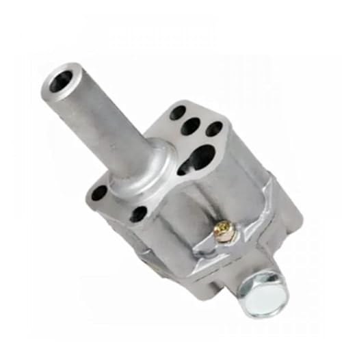
Low oil pressure on an L24 is not a “watch it for a few days” situation. The oil pump is the engine’s only defense against metal-to-metal contact at the crank, cam, and rod bearings, and a worn pump that can’t hold pressure will destroy those bearings quietly before the gauge needle moves far enough to alarm anyone. The good news: the pump on the S30 is accessible without pulling the engine, the job is straightforward, and the factory inspection clearances tell you definitively whether the pump is worth keeping or needs replacement.
How the System Works
The L24 runs a rotor-type oil pump — an inner drive rotor and an outer driven rotor, both sitting inside a machined body bolted to the underside of the timing chain front cover with four bolts. As the rotors turn, the volume between their lobes grows and shrinks, drawing oil in from the sump through a strainer and pushing it out under pressure to the full-flow filter and main gallery.
Drive comes from the crankshaft through a gear that spins the distributor drive shaft. That shaft drops into a slot at the top of the pump drive rotor, so the oil pump and distributor share a driveline. This matters at installation: you have to set the crankshaft to TDC before the pump goes back in, or the distributor will end up clocked wrong.
A non-adjustable pressure relief valve in the pump cover limits maximum output pressure. When pump pressure exceeds the relief spring’s opening load, the valve opens and recirculates oil back to the inlet side. If you’re fighting either low or erratically spiking oil pressure, start by checking pump wear clearances and relief spring dimensions before hunting elsewhere.
Specs at a Glance
| Parameter | Metric | Imperial |
|---|---|---|
| Oil pressure at idle | 1.0–1.2 kg/cm² | 14.2–17.1 psi |
| Rotor side clearance (outer to inner rotor) | 0.05–0.12 mm | 0.0020–0.0047 in |
| Tip clearance (inner rotor lobe to outer rotor), max | 0.12 mm | 0.0492 in |
| Outer rotor to body clearance | 0.15–0.21 mm | 0.0059–0.083 in |
| Relief valve opening pressure | 3.8–4.2 kg/cm² | 54.0–59.7 psi |
| Relief valve spring, free length | 57 mm | 2.24 in |
| Relief valve spring, pressured length | 39 mm | 1.54 in |
| Oil pump mounting bolt torque | 1.5–2.1 kg-m | 10.8–15.2 ft-lb |
| Relief valve cap nut torque | 3.0–3.5 kg-m | 21.7–25.3 ft-lb |
Tools and Parts
| Part | Recommended part | |
|---|---|---|
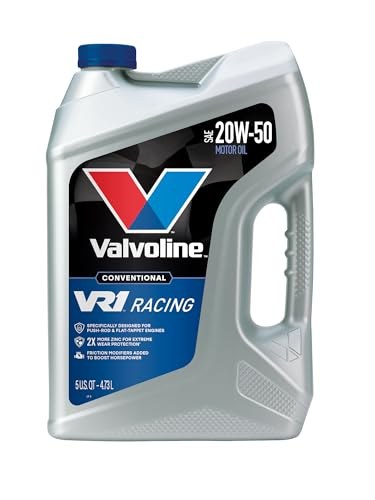 | Engine oil (vintage-friendly) | Buy on Amazon ↗ |
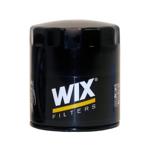 | Oil filter (Wix 51068) | Buy on Amazon ↗ |
| Oil pump | Buy on Amazon ↗ |
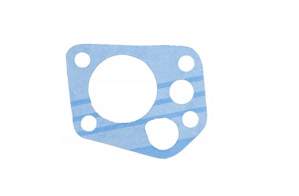 | Oil pump gasket | Buy at ZCarDepot ↗ |
| Tool | Buy | |
|---|---|---|
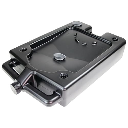 | Drain pan and funnel 12-quart low-profile pan; oil pump removal will release ~4–5 quarts. | Buy ↗ |
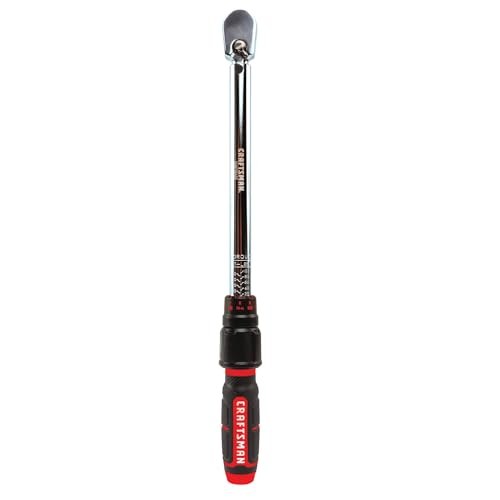 | 1/2″ drive torque wrench, 0–25 ft-lb range Mounting bolt spec is 10.8–15.2 ft-lb; 3/8″ drive in this range gives clean control. | Buy ↗ |
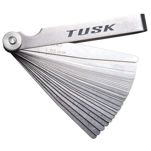 | Metric feeler gauge set Rotor side clearance 0.05–0.12 mm and tip clearance ≤0.12 mm — both need 0.05 mm resolution. | Buy ↗ |
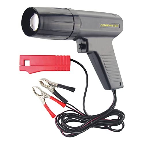 | Inductive timing light For verifying oil pump drive alignment after install (ignition timing returns once the distributor reseats on the oil pump shaft). | Buy ↗ |
Also:
- Floor jack and jack stands (or a lift)
- Metric socket set, 8 mm – 17 mm
- Flat-blade screwdriver
- Straight-edge or machinist’s ruler (for side clearance measurement)
- Rubber mallet, gasket scraper, clean shop rags
Removal (Engine in Vehicle)
1. Prep and disconnect. Let the engine cool. Disconnect the negative battery terminal. If you have a mechanical oil pressure gauge, leave the engine-side fitting connected for the pressure check after reinstallation.
2. Remove the distributor. Before you pull it, mark the rotor tip position on the distributor body, and mark the distributor body position relative to the front cover. This gives you a reference for reinstallation. Remove the distributor hold-down clamp and lift it straight out.
3. Drain the oil. Position a drain pan and remove the drain plug. Let the pan drain completely — the front cover area will still have residual oil and you don’t want it running into the pump bore when you pull the assembly. This is a good time to remove and discard the old oil filter.
4. Drop the splash shield. The underside panel below the front of the engine is held by several bolts along the subframe. Remove it to get clear access to the pump.
5. Pull the pump. Locate the oil pump on the underside of the front cover — four bolts, cylindrical body with the drive spindle protruding upward. Remove the four bolts and pull the pump body downward, bringing the drive gear spindle out with it as a unit.
Disassembly and Inspection
If you’re doing a straight swap to a known-good pump, skip to Installation. If the pump is coming apart for inspection, continue here.
6. Open the pump body. A single bolt secures the body cover to the pump body. Remove it and lift the cover off. Slide the drive rotor and outer driven rotor out of the body.
7. Clean before measuring. Wash all parts in solvent and dry them thoroughly. Any oil film will give you falsely small clearance readings on the feeler gauge.
8. Inspect the drive rotor shaft for scoring, galling, or step wear where the shaft runs in its bore. Light surface marks are acceptable; any groove you can catch a fingernail in is not.
9. Check rotor side clearance. Lay a straight-edge flat across the face of the pump body. Using a feeler gauge, measure the gap between the straight-edge and the top face of the outer rotor — this is your side clearance (axial play between the rotors and the body face). The specification is 0.05–0.12 mm (0.0020–0.0047 in). A reading at or past 0.12 mm means the pump is bleeding volume around the rotor faces and should be replaced.
10. Check tip clearance. With the rotors seated in the body, measure the gap between a lobe tip of the inner rotor and the adjacent surface of the outer rotor at their closest approach. Maximum allowable is 0.12 mm. Near or past this limit, replace the pump.
11. Check outer rotor to body clearance. Slide the feeler gauge between the outer edge of the outer rotor and the pump body bore. Specification is 0.15–0.21 mm (0.0059–0.0083 in). A rotor that’s worn undersized or a bore that’s worn oversized will show up here.
12. Measure the relief valve spring. Free length should be 57 mm (2.24 in). A spring that measures short has taken a set and will open at lower pressure than spec, causing chronically low oil pressure at idle. Replace any spring that’s more than 1–2 mm short at free length.
Reassembly
13. Install the rotors. Reinstall the drive rotor and outer driven rotor in the pump body in the same orientation they came out. There’s typically a dot or chamfer mark on the outer rotor face — confirm it faces the same direction as before.
14. Install the cover. Lay the cover gasket flat on the pump body face. Do not fold, crease, or reuse a gasket that was previously disturbed — a deformed gasket will leak. Set the cover down and snug the single securing bolt.
Installation
15. Set the crankshaft to TDC, No. 1 cylinder. Rotate the crankshaft until the timing marks on the front pulley align with the “0” mark on the front cover pointer and you’re on the compression stroke for cylinder No. 1 (both rocker arms for No. 1 should be resting — neither valve open). The distributor will clock itself off this position when reinstalled, so this step has to be right.
16. Orient the drive spindle. The drive gear spindle has a punched mark (a small dimple) on its body. Face that mark toward the front of the engine before dropping the assembly into the front cover. This is the index mark the factory uses to align the distributor drive.
17. Seat the pump. Lower the pump and spindle assembly into the front cover bore. Confirm that the dog at the lower end of the distributor drive shaft has engaged the slot in the top of the pump drive rotor — you can see this by looking straight down through the distributor mounting hole. Do not torque the mounting bolts if the pump hasn’t fully seated; a pump that’s sitting on top of the drive dog rather than engaged with it will look flush but will not drive.
18. Torque the mounting bolts. Install the four mounting bolts finger-tight first, then torque in a crossing pattern to 1.5–2.1 kg-m (10.8–15.2 ft-lb). The front cover is cast aluminum — stop at 15.2 ft-lb.
19. Reinstall the distributor. Align the body to your reference marks from Step 2 and drop it into the front cover. Reinstall the hold-down clamp but leave it slightly loose — you’ll need to rotate the distributor body to set timing after startup.
20. Install the oil filter. Thread the fresh filter on by hand until the gasket contacts the block, then turn it an additional three-quarter turn. That’s the correct preload. Overtightening causes the filter gasket to split and leak; the filter doesn’t need to be torqued like a bolt.
21. Refill the engine. Install a new drain plug washer, reinstall the drain plug and torque to spec. Fill the engine with the correct quantity and grade of oil. Reinstall the splash shield.
Common Mistakes
Installing with the crank off TDC. The distributor will be clocked to the wrong cylinder and the engine may crank without starting, or will run with badly retarded ignition timing. Set TDC before anything else.
Ignoring the spindle punch mark. If the spindle goes in 180° out, the distributor rotor will point at the wrong cap terminal at TDC. The engine will often still start but with the wrong cylinders firing at the wrong time. Always face the mark forward.
Reusing a disturbed gasket. The pump body cover gasket is thin and takes a permanent set once compressed. A refitted used gasket nearly always leaks. Keep new gaskets on hand.
Skipping the engagement check. You can’t feel a missed drive-dog engagement through the pump body. Look down the distributor hole before torquing the mounting bolts.
Over-torquing the mounting bolts into aluminum. 15 ft-lb maximum. If a bolt feels tight before you reach torque, stop, remove it, and check for thread damage in the front cover.
Verification
22. Prime before first start. Disconnect the wire from the ignition coil (or pull the fuel pump relay on an EFI car if fitted). Crank the engine for 5–10 seconds — this spins the pump and primes the galleries before any combustion load is placed on the bearings. Watch the oil pressure gauge. If you have a mechanical gauge, pressure should register within a couple seconds of cranking.
23. Start and confirm pressure. Reconnect the coil wire and start the engine. Oil pressure at idle should settle at 1.0–1.2 kg/cm² (14.2–17.1 psi) on a mechanical gauge. If the idiot light stays on after two seconds of running, shut the engine off immediately and don’t restart until you’ve identified the cause.
24. Check for leaks. With the engine at idle, inspect the pump mounting face and the oil filter base. Let the engine reach operating temperature, then recheck both. A slow seep that doesn’t show up cold will usually appear within the first ten minutes of heat cycling.
25. Set ignition timing. With the engine at operating temperature and the vacuum advance disconnected, connect a timing light to cylinder No. 1 and set initial timing per spec. Reconnect the vacuum line.
Maintenance Interval
The oil pump has no factory-scheduled replacement interval — it’s inspected when it’s out, not on a calendar. What shortens pump life faster than mileage is degraded oil: extended drain intervals leave abrasives in suspension and starve the clearances of a protective film. Keep to a 3,000–4,000 mile oil change interval on a street-driven S30 and the pump will outlast most other components. Replace the oil filter every 6,000 miles (10,000 km) at minimum.
