This is the first guide in a series of many on completely repairing, rebuilding, and tuning your Datsun 240Z’s SU carburetors. I’d recommend you check out all the different guides we have on this topic. These carburetors are a headache for many when it comes to working on their 240Z, and we want to demystify this process. The most logical first step in this, is to make sure you understand the basic design and functionality behind the SU carburetor and how dual carburetor setups work, and this guide will focus on that.
Some of the links on ZCarGuide page may be affiliate links, meaning I receive a commission (at no extra cost to you) if you click on the link and make a purchase. I only recommend products I’ve used and trust unless stated otherwise.
Before we get into the inner-workings of an individual SU carburetor, you should know that the SU carburetor is known as a constant depression or constant vacuum type carburetor. This means that the vacuum over the jet is generally constant regardless of the kind of airflow requirement of the engine. If that didn’t really make any sense, don’t sweat it — it’s just a good way to preface this guide. All you need to remember is that the general area inside of your carburetor is generally a vacuum, meaning it has all/most of the air pumped out of it and it is free from pressure. More specifically, there is an area known as the ‘constant depression zone’ between the piston and the throttle butterfly, so you may seen that referred to in different books and guides.
Take a look at the diagram below which details the theoretical design behind the SU carburetor. It’s very dumbed down, but hopefully that will make it a bit easier to explain how it works, step by step. Additionally, I’ve included a real picture of one of my SU carbs as we will start by helping you match up the components in my diagram, to the real components in an SU carburetor.
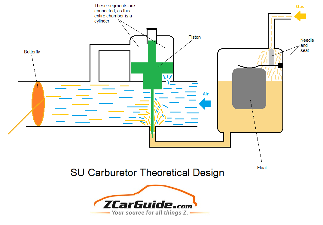
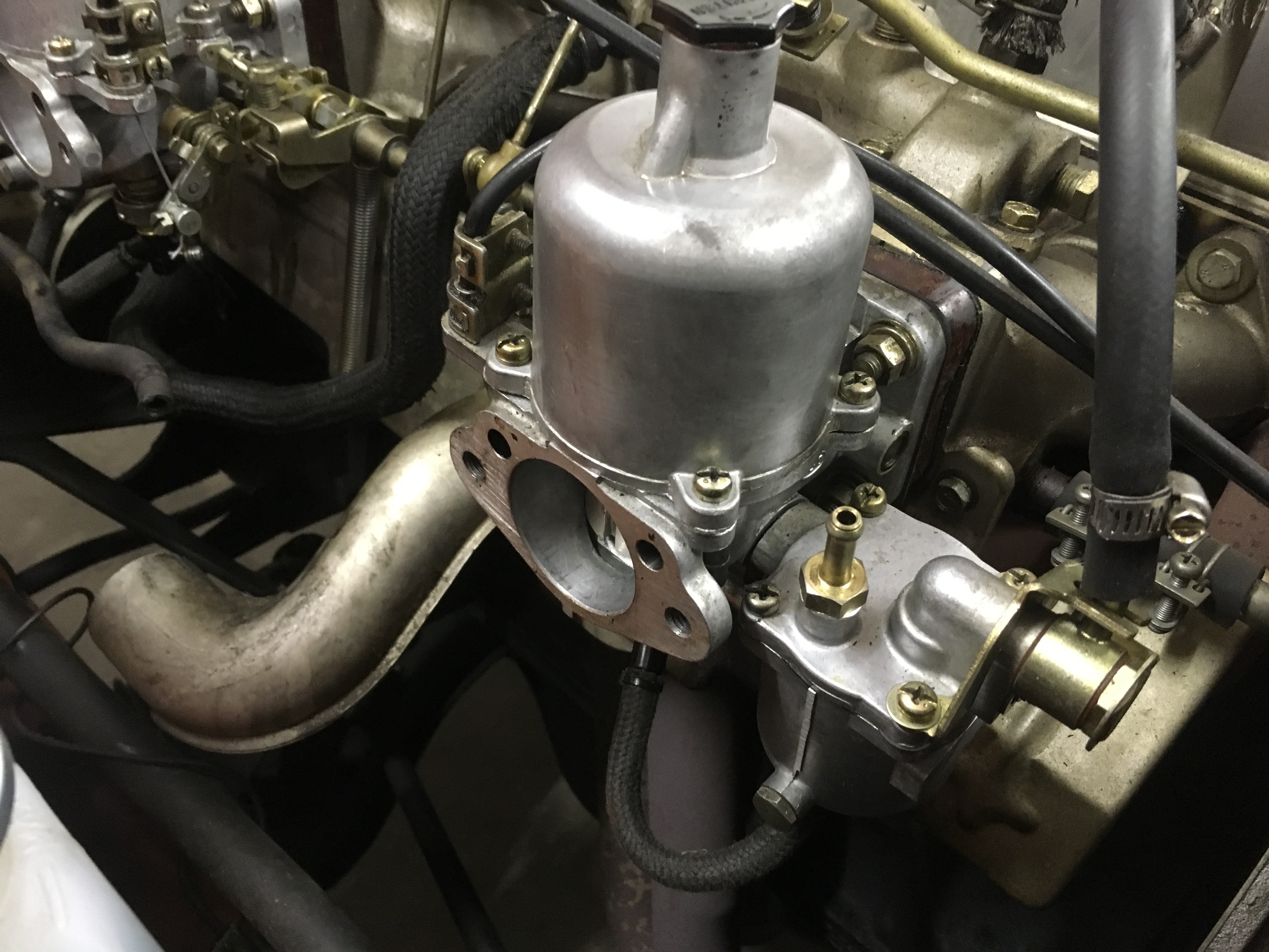
So, let’s start off by matching up these components, if you haven’t gotten a grasp of that already. The float chamber, which houses the float in the diagram, is the little chamber to the right of the carburetor in the real picture. This is helpful because you can also match up the braided fuel line in the real picture, to the line in the diagram which connects the float chamber to the carburetor. Next, the opening you see in the real picture, is obviously the right side of the carburetor bridge in the diagram, where the air is coming in. Everything else at this point should be easy to match up, and now we’ll go over how the carburetor functions and delivers the correct fuel mixture to your engine!
Functionality of the SU Carburetor
Start by focusing on the end of the carburetor bridge, to the left of the butterfly. This is where the carburetor bridge connects to the engine itself and delivers a properly balanced mix of fuel and air. Due to the suction of the engine, this particular area (to the left of the butterfly) is under a great deal of depressurization, meaning it can be called a vacuum. It is important to note that vacuum technically refers to a space completely devoid of matter, but it is often loosely used to describe an area that is generally quite depressurized, as a 100% vacuum is extremely rare in reality.
Another key concept here is that the engine itself plays into this depressurization a lot. For the context of this guide, you can think of the engine as a large pump, that constantly sucks in air. When we are idling, the butterfly will be almost completely closing off airflow to this left side, although some air must go through in order to keep the engine alive. Another important thing to remember at this idling stage is that the right side of the engine is much closer to atmospheric pressure, and definitely more pressurized than the left side. However, when we press the throttle pedal, this butterfly opens up a bit and the relationship between the two sides becomes much more important. Because the left side of the butterfly has little to no pressure (due to our engine ‘pump’), and the right side has far more pressure, air will rush into the left side in an attempt to equal out pressure between the two halves.
So, you understand how the butterfly creates this airflow effect across the bridge of the carburetor, and how the butterfly facilitates a lot of this. Next, take a look at the chamber above the piston (the piston is colored green in the diagram) and you will see that it is connected to the carburetor bridge to the right of the butterfly, meaning its level of pressure is connected. When this air rushes out of the right side, and into the left side in order to balance out pressure, this chamber above the piston is affected in the same manner. Air rushes out of that chamber above the piston, leading to a vacuum in that area! Additionally, note the hole that connects the chamber below the piston, to atmospheric pressure. Because of the pressure differential above and below the piston, the piston will rise! What exactly does it mean when the piston rises or falls?
You can see that the piston features a long needle on the bottom of it which juts down into the tube through which fuel is flowing from the float chamber. That tube spits out minuscule amounts of fuel which mix with the airflow, as the air passes across it. This is how we get our gaseous fuel that is critical for engine combustion. If the word ‘Venturi’ is unfamiliar to you, you should read up on the subject a bit to understand how the fuel is pulled from the fuel line as airflow is accelerated and air rushes across the jet. This is great, but how does the needle affect this, and why is it even necessary? This needle is tapered, meaning that the further up the piston and needle are, the larger the passageway through which fuel can disperse out of the tube. When the piston is all the way down (occurs while vehicle is idling) the needle is almost completely inserted into the tube, and because the needle is thickest at the top, it is blocking a lot of the tube through which fuel disperses. When the piston is at its highest point, the skinniest portion of the needle is inside the tube, meaning the area that fuel has to disperse out of, is much larger! The needle is tapered and this creates an infinite number of positions which dictate the fuel flow out of the tube. This is important because the engine has different fuel requirements for many different stages of operation.
SU Carburetors Used on the 240Z
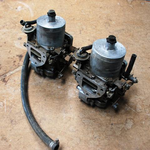
Throughout the entire production run of the 240Z, it used two different types of SU carburetors. Most SU carburetors in that day and age were actually built by The S.U. Carburettor Company Ltd., but Hitachi also built carburetors based off of the SU design. Hitachi produced two carburetors that were used on the 240Z and 260Z. The most common Hitachi SU carburetor seen on the 240Z is the HJC46W ‘Round Top’ carburetor. Towards the end of the 240Z production, and most of 260Z production, Datsun began to use the Hitachi HMB 46W ‘Flat Top’ carburetor.
The primary difference between the two is that the HMB 46W featured an HIF design, which stands for ‘Horizontal Integrated Float’. This means that the float chamber is actually integrated within the body of the carburetor, instead of as a separate unit as seen on the HJC46W. These flat top SU carbs were far less reliable than the round top variants, and are generally much more difficult to tune. Many 240Z and 260Z owners actually opt to completely discard their flat-top carbs to swap in round tops, or even some ZTherapy refurbished carbs. This guide will focus on working with round top Hitachu SUs as the vast majority of 240Z and 260Z owners run these carbs, but we will definitely do our best to help those who wish to tune their flat top carbs.